The following tasks/steps should be followed to successfully install an AF-6600 / AF-5000
based system in the aircraft. Detailed information of installation, calibration, component
wiring… is found in sections of this manual.
1. System Block Diagram
The first thing you should do is make a block diagram of all the components that will be connected in
the aircraft. The block diagram should include all the EFIS screens, Radios, GPS units, Transponder,
AP, and ADS-B Receiver. The block diagram should clearly indicate where each EFIS screen’s serial
ports will be connected to each piece of equipment.
EFIS RS-232 Serial Port Planning
Each AF-6600 or AF-5000 EFIS has Qty (5) RS-232 serial ports.
The following requirements should be followed:
• A GPS Navigator (IFD540, IFD440, GTN650, GTN750) will need an SV-ARINC-429 module
• The Transponder should be wired to a PFD RV-232 Serial Port
• If the aircraft has two Nav radios each one should be wired to a different screen for backup
reliability.
• If the aircraft has two GPS units each one should be wired to a different screen for backup
reliability.
• You can’t have XM and ADS-B weather with a single screen system.
2. Advanced Skyview Network Planning
Most of the AFS - Dynon components communicate using our proprietary SV-Network. The SV-Network
provides a primary and backup +8 Volt power source and a primary (A) and backup (B) two wire network
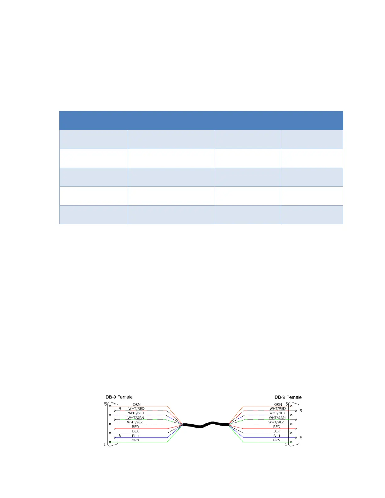
for the remote devices. The SV-Network is designed to use 9 pin DSUB connectors and a special 9
conductor cable. The AFS-Dynon components all use a 9 Pin DSUB connector with male pins. The SV-
NET harnesses all use a 9 pin DSUB connector with female pins. The SV-Network is designed to be a
parallel network that does not require any special terminations. As long as all components are
connected together in a single network they should communicate. Some of the Dynon components
have two SV-Network connectors so you can continue the network connection to the next device. You
can use multiple Dynon 5 port hubs connected if you need more ports.
SV-NET CABLE
• The following devices should be connected to the SV-Network using the standard SV-NET
cables: AF-6600, AF-5000 , SV-ADAHRS-200, SV-ADAHRS-221, SV-AP-PANEL, SV-KNOB-
PANEL, ACM-ECB, SV-COM-RADIO, SV-ARINC-429