Version 16.10 AF-6600 AF-5000 Series Install Manual 18
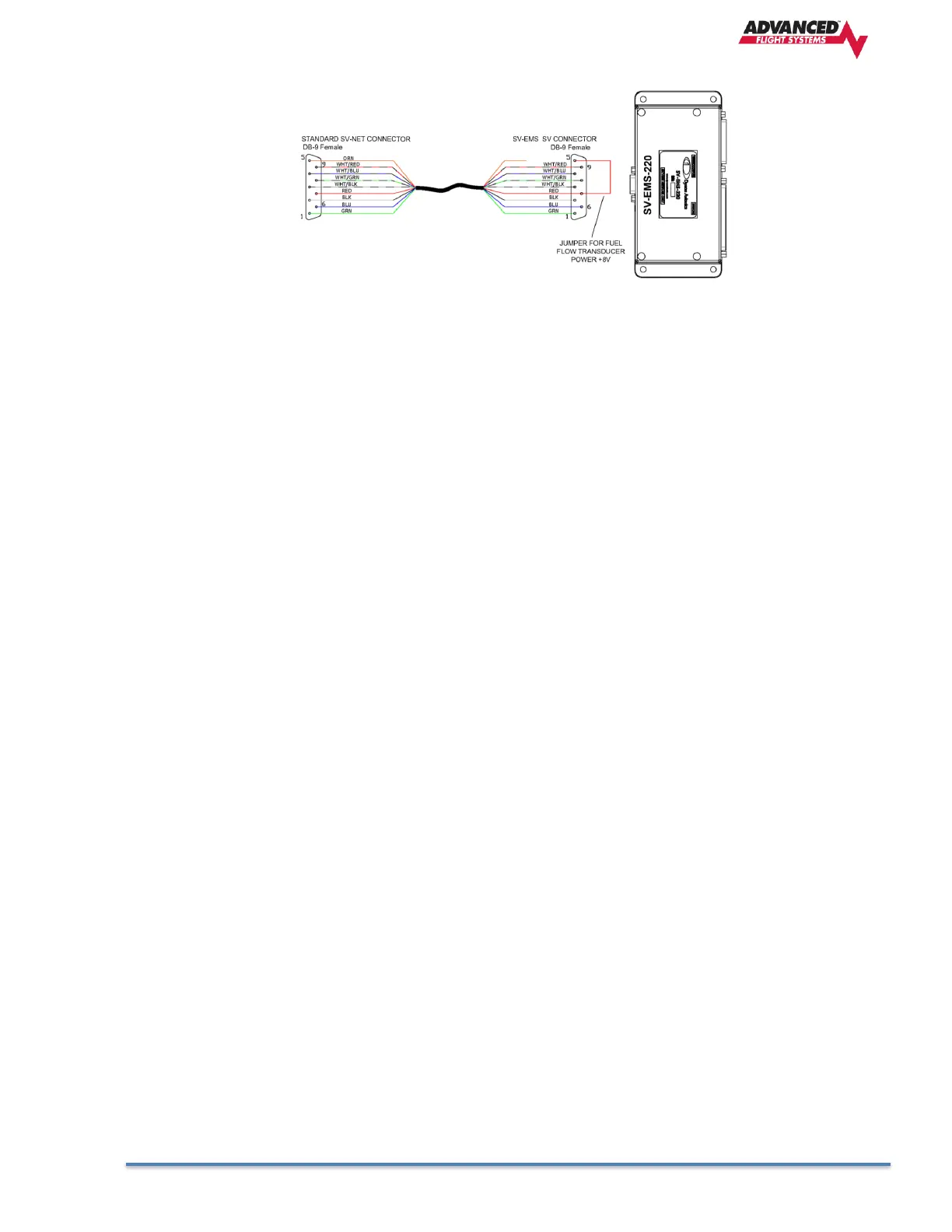
• The SV-EMS-220 or SV-EMS-221 require a special SV-NET cable with a jumper on the SV-
EMS end of the cable to power the fuel flow transducer.
• The Dynon Autopilot servos connect to only the SV-Network data pins and will use a dedicated
fused +12V power connection.
3. Component Locating and Mounting
Find convenient mounting locations for all the components: EFIS Screens, ADAHRS, Transponder,
ADS-B… keeping in mind that they might need to be removed for service after the aircraft is finished.
The EFIS screens should be mounted from the front of the panel using the supplied 6-32 screws. It is
highly recommended that you use 6-32 PEM or Nut Plates for screen mounting to the instrument panel.
4. Component Power and Ground Wiring
Connect each EFIS screen and component to a separate properly sized fuse or circuit breaker. Each
EFIS screen MUST have the backup power wired to a backup battery or fused direct aircraft battery
connection. All EFIS screens and components should be wired to a good ground connection.
5. Screen RS-232 Serial Port Wiring
Using your block diagram wire the EFIS Screen(s) serial ports to the external equipment.
6. Screen Digital Inputs and Output wiring
a. Digital inputs are shared between screens, if you are using the inputs for door or canopy warning
they should be wired to the PFD screen.
b. Inputs used for Landing Gear should be wired to the PFD
c. Inputs should be wired to a switch that connects to ground to activate.
d. The Digital Output is designed to be used with a warning light and will connect to ground anytime an
EFIS warning is activated.
7. EFIS Audio Wiring
Connect only the Audio from the Pilot EFIS screen to an unswitched audio panel input. Do not connect
the audio from any other EFIS.
8. Pitot-Static- AOA Plumbing
ADAHRS Pitot and Static connections are standard 1/8” NPT. Double check that you don’t have them
reversed!
9. Ethernet Wiring
The Ethernet connection is a Standard CAT 5 cable between screens. If you are using more than one
screen and/or Ethernet XM weather you will need to use a separate Ethernet Switch.
10. Engine Sensor Installation and Wiring
Wire each engine sensor to the Engine Module using the sensor wiring schematic.