Version 16.10 AF-6600 AF-5000 Series Install Manual 44
Linkage Mount Position Force and Travel
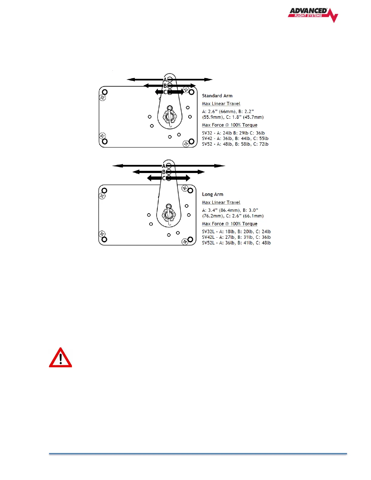
The two diagrams below illustrate the maximum travel and force available at each linkage mounting
point. As can be seen, the closer you mount the linkage to the shaft, the more force the servo can
deliver. However, this also means the travel of the arm is shorter.
Again, ensure that the servo arm is nowhere near going over-center throughout the entire range of the
control system.
The maximum linear travel specifications called out above denote the distance traveled by the location
on the arm such that it is 60° from center at maximum distance in either direction (e.g., the A hole on
the standard servo arm can linearly travel 1.3”(33mm) from center in either direction).
During installation, the linkage hardware must be connected to the servo arm such that the servo can
actuate the connected control surface while approaching, but not exceeding the called out maximum
linear travel specification. If too much slippage occurs during servo flight testing, it may be necessary
to use a stronger servo.
Each Dynon Avionics servo includes a precision-machined brass shear screw that pins the
servo arm to the servo arm attachment, providing an ultimate manual override. Servo
shear screws will break at the application of 100 inch-pounds of torque, at which point
the servo arm will travel freely. If the brass shear screw is broken during autopilot
installation or usage, do not replace it with a standard screw– contact Dynon Technical
Support (contact information at the beginning of this manual) for a replacement shear
screw. Instruction for replacing the shear screw can be found at
http://docs.dynonavionics.com.