Version 16.10 AF-6600 AF-5000 Series Install Manual 47
Electrical Installation
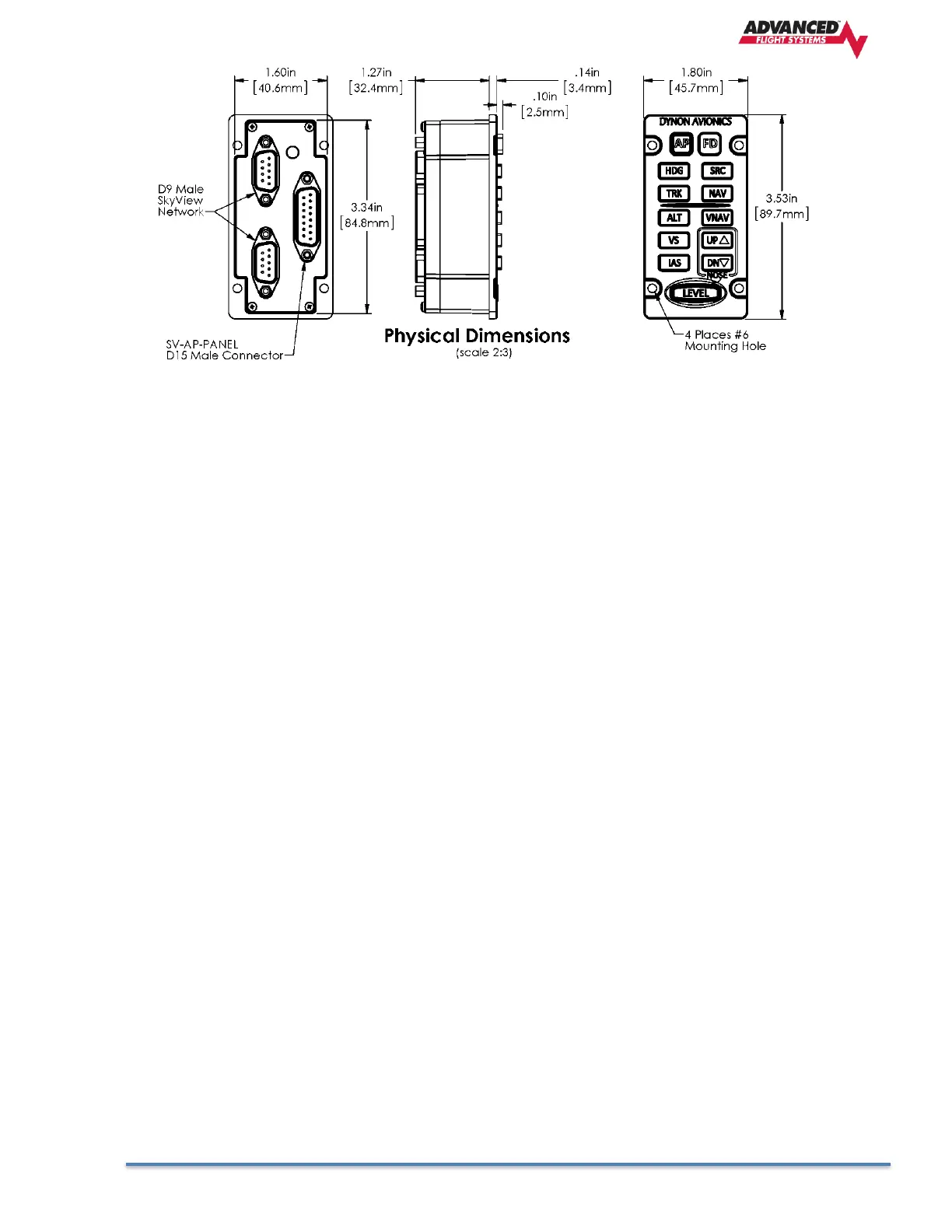
SV Network The SV-AP-PANEL has two SV Network connections (D-9 connectors). Both connectors are
electrically identical and are internally connected. Thus, the SV-AP-PANEL can be installed in the SV
Network as a “pass-through” device, or “daisy chained” from one SV Network device, through the SV-
AP-PANEL, to the next SV Network device. The SV-NET-1.5CC is an 18-inch SV Network cable that is
ideal for such situations. The SV-AP-PANEL receives power (for operation of the buttons) from SV
Network. Dimming of the SV-AP-PANEL is controlled by the AF-5000 display(s).
Trim Motor Control In addition to the AP mode buttons, the SV-AP-PANEL includes an
adjustable, speed-sensitive trim controller, eliminating the need for relay packs or a
separate trim controller. The integrated trim controller is wired to a D15 connector that
can be connected to Aircraft power (12V only), pushbuttons (typically, on the stick),
and power to and control of up to two trim motors - such as those made by Ray Allen.
A set of pushbuttons can optionally be installed for the copilot. The pilot’s pushbuttons
take priority over the copilot’s pushbuttons. Pushbuttons used for Trim Motor Control
must be Push Button Normally Open (PBNO) – a momentary switch with a contact that
is closed only when the button is pushed. One terminal of the pushbutton is connected
to the selected pin, the other terminal of the pushbutton is connected to avionics
ground (can be common with Pin 2).
Note that the SV-AP-PANEL’s trim controller only connects to the trim motors. The SV-
AP-PANEL does not connect to or monitor trim position. Monitoring trim position is done
by connecting the trim motor’s potentiometer (position sensor) that is mechanically
ganged to the trim motor to a Trim Input pin on the AF-5000 EMS connector.
Trim Motor Control Safety Features
• Pilot trim controls override Copilot trim controls.
• If SV Network connection or AF-5000 power is lost, the trim motor functions will continue to
function as long as avionics power is available at Pin 9. When a AF-5000 is not powered on (not
communicating with the SV-AP-PANEL) the speed scheduling features (QUICKEST TRIM SPEED /
SLOWEST TRIM SPEED) are not available. In this failsafe mode, the trim motors will run at their
full speed when trim buttons are pushed.
• If a trim control button is detected as pushed when power is first applied to Pin 9, trim control
will not activate until the button is first released.