Version 16.10 AF-6600 AF-5000 Series Install Manual 48
• If a trim control button is pushed for more than five seconds (or longer, such as a stuck button),
trim control on that axis will be temporarily inactivated until the button is first released.
• Motor outputs are protected against short circuits.
If two SV-AP-PANELs are installed, connect only one SV-AP-PANEL to control trim motors. Do not
connect the second SV-AP-PANEL’s D15 connector in parallel with the first SV-AP-PANEL’s D15
connector – doing so could cause unexpected behavior and/or damage to the units and the trim
motors.
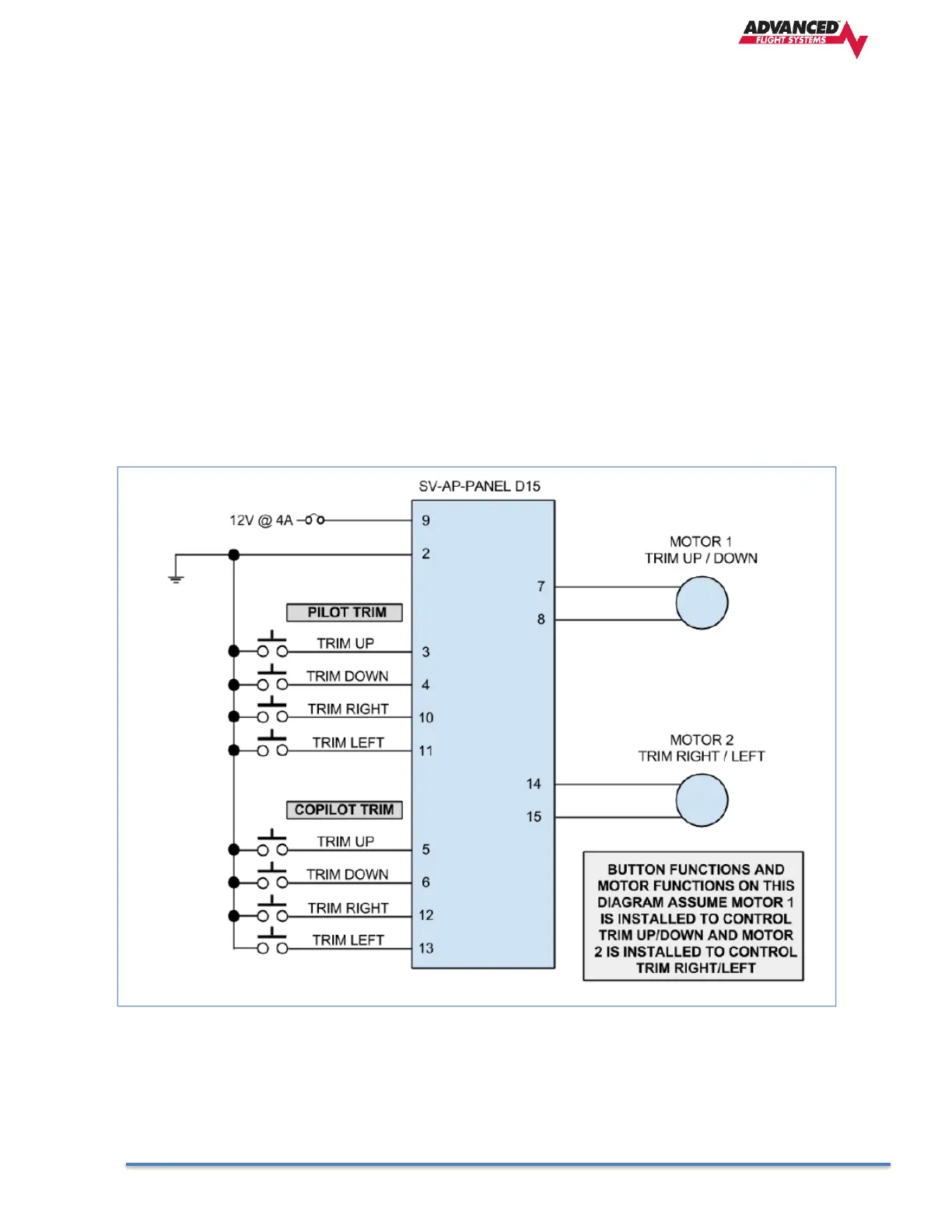
On the D15 connector, Power (Pin 9) and Ground (Pin 2) connections are only required to control a
Pitch trim motor and/or a Roll trim motor. If the trim motor outputs are not used, Power (Pin 9) and
Ground (Pin 2) should not be connected.
Ray Allen trim motors are known to work - connect the white wires to Pins 7 and 8 (MOTOR 1) and/or
Pins 14 and 15 (MOTOR 2). If using other trim motors, ensure that the trim motor’s maximum current
does not exceed 2A.
The functions assigned to each pin in Table 69 below reflect Motor 1 being used for TRIM UP/DOWN
and Motor 2 being used for TRIM RIGHT/LEFT.