EasyManua.ls Logo

Advanced AF-6600 - Page 69

Advanced AF-6600
267 pages
Print Icon
To Next Page IconTo Next Page
To Previous Page IconTo Previous Page
Loading...
Version 16.10 AF-6600 AF-5000 Series Install Manual 69
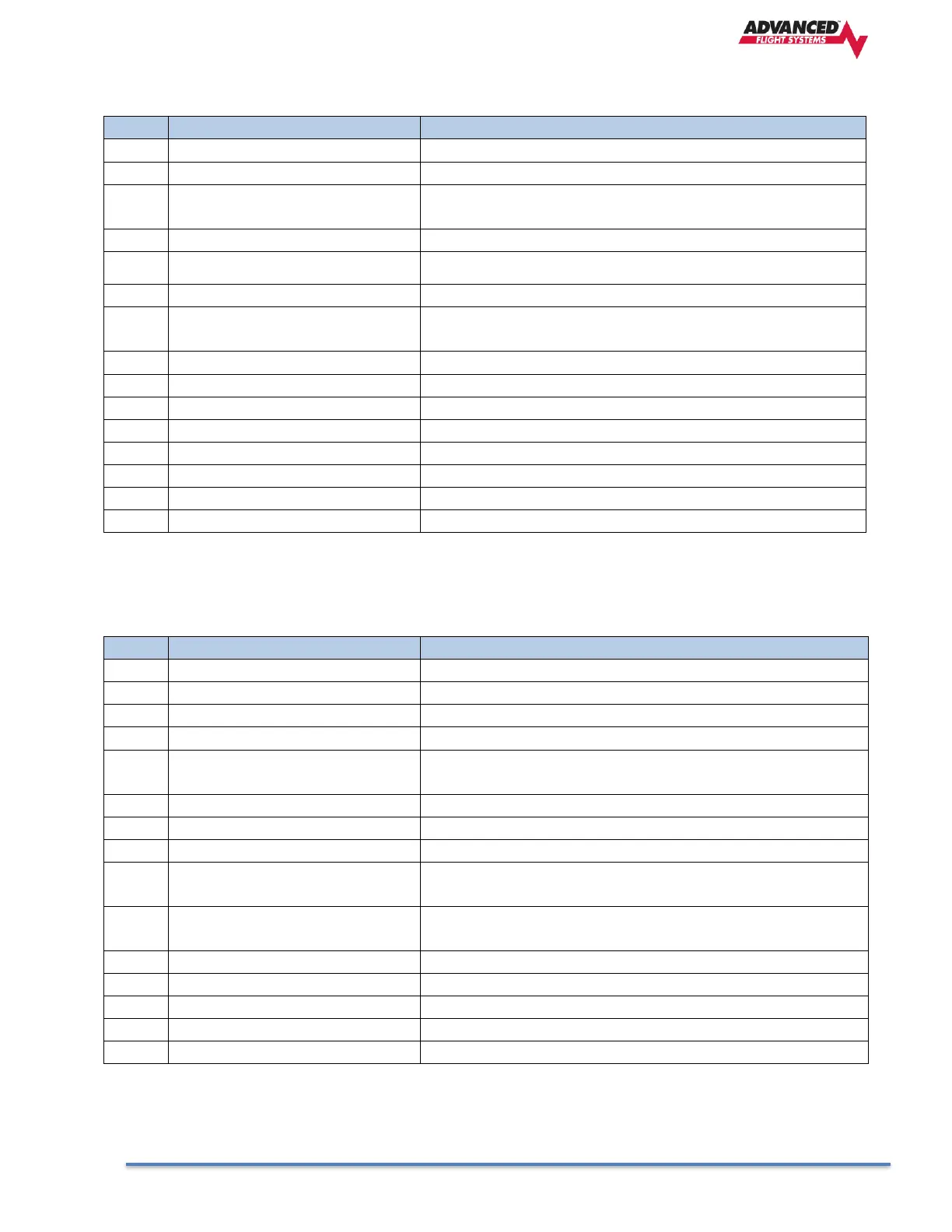
AF-COM-PANEL Pinout (Male D15)
Pin
Function
Notes
1
Power In
From AF-COM-425 Pin 7
2
Ground In
From AF-COM-425 Pin 13
3
Ground Out
Optional - For Grounding Pin 7 (Flip/Flop Switch). Switch
may also be grounded locally.
4
Panel RX / 425 TX
From AF-COM-425 Pin 6
5
Panel TX / 425 RX
From AF-COM-425 Pin 14
6
Enable
From AF-COM-425 Pin 3
7
External Flip/Flop (optional)
Push Button Normally Open to Ground (Pin 3 or local
ground)
8
No Connection
(Pin not used)
9
No Connection
(Pin not used)
10
No Connection
(Pin not used)
11
No Connection
(Pin not used)
12
No Connection
(Pin not used)
13
No Connection
(Pin not used)
14
No Connection
(Pin not used)
15
No Connection
(Pin not used)
Dynon-COM-T25/T8 Pinout (Male D25)
Pin
Function
Notes
23
MICROPHONE IN
AF-INTERCOM-2S Pin 25
9
MICROPHONE / PTT GROUND
See diagram below.
13
AF-COM-PANEL ENABLE
To AF-COM-PANEL Pin 6
15
PTT IN
AF-INTERCOM-2S Pin 12 or Push Button Normally Open
(PBNO) to Ground (Pins 4, 11, or 15)
6
DATA TX to AF-COM-PANEL
To AF-COM-PANEL Pin 4
AF-COM-PANEL POWER
To AF-COM-PANEL Pin 1
24,25
POWER IN
10-30V DC @ 5A
1
PHONES GROUND
AF-COM-425 Pin 2 AF-INTERCOM-2S Pin 1 Shielded Cable
shield of Pin 10
2
PHONES OUT
AF-INTERCOM-2S Pin 14 Shielded Cable center conductor
of Pin 10
19
GROUND IN
Connect to Ground Bus
22
GROUND IN
Connect to Ground Bus
5
DATA RX from AF-COM-PANEL
AF-COM-PANEL Pin 5

Table of Contents