Version 16.10 AF-6600 AF-5000 Series Install Manual 72
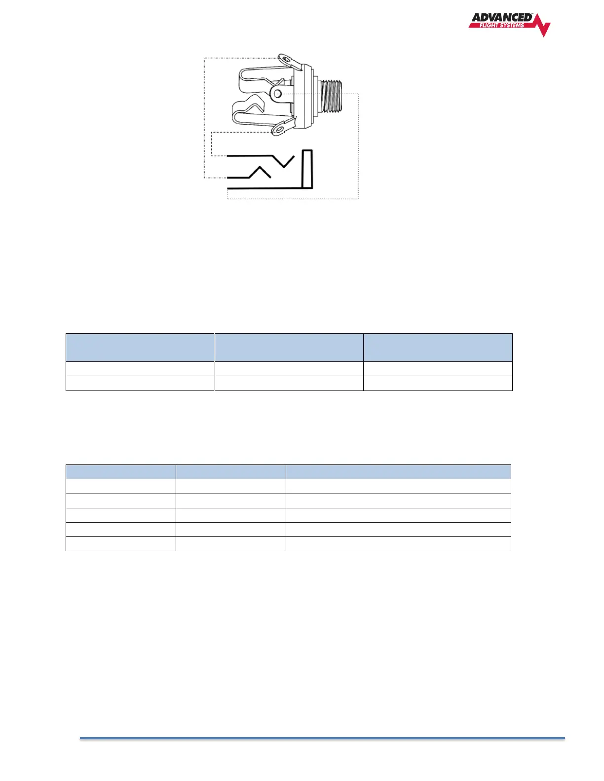
Headset Jack Schematic
Power/Ground Input
The SV-COM-T25/T8 requires 10-30V DC. For wire runs from power distribution to the SV-COM-T25/T8
up to 6’, 22 AWG wire is sufficient for power and ground wires. For wire runs from power distribution
to the SV-COM-T25/T8 longer than 6’, 20 AWG wire is recommended for power and ground wires. For
the cable between the SV-COM-T25/T8 and the AF-COM-PANEL, 22 AWG power and ground wire is
sufficient. Use a 5 Amp fuse or circuit breaker for power supply protection to each SV-COM-T25/T8.
Approximate current
consumption at 12 volts DC
Approximate current
consumption at 24 volts DC
AF-COM-PANEL TO AF-COM-T25 Interconnections
ENABLE SV-COM-T25 -> SV-COM-PANEL
POWER SV-COM-T25 -> SV-COM-PANEL
GROUND SV-COM-T25 -> SV-COM-PANEL
DATA OUT SV-COM-PANEL -> SVCOM-T25)
DATA IN SV-COM-T25 -> SV-COM-PANEL
Optional Flip / Flop Button
Pin 7 of the AF-COM-PANEL can be connected to a Push Button Normally Open (PBNO) and GROUND.
Pushing this button “flip flops” the ACTIVE and STANDBY frequency selection - the same function as
pressing in the TUNE knob on the AF-COM-PANEL. Typically this signal is used with a button on the
stick.