Introduction to the Fluorescence Detector 7
1100 Series FD Reference Manual 247
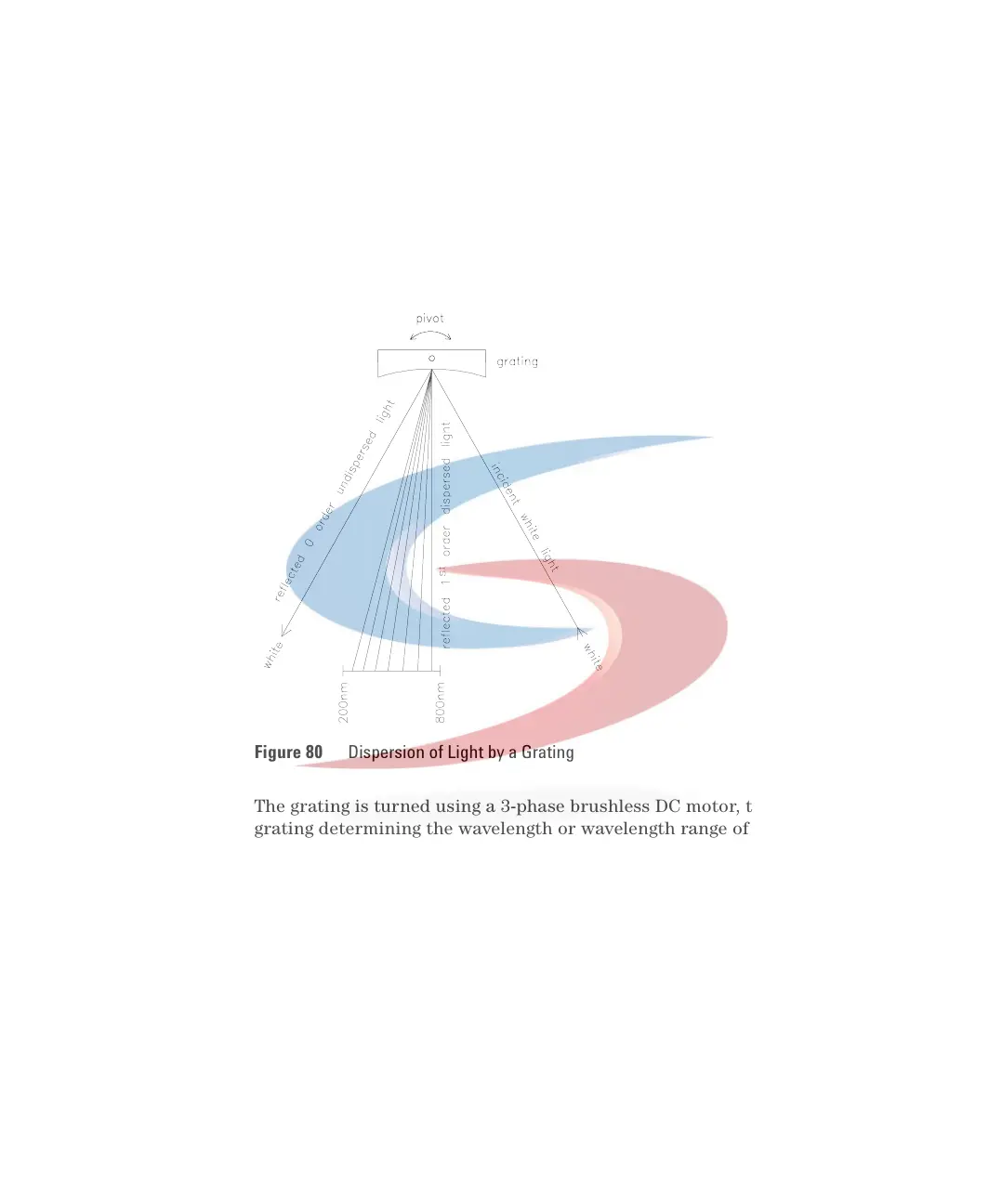
The geometry of the grooves is optimized to reflect almost all of the incident
light, in the 1
st
order and disperse it with about 70% efficiency in the
ultra-violet range. Most of the remaining 30% of the light is reflected at zero
order, with no dispersion. Figure 80 illustrates the light path at the surface of
the grating.
The grating is turned using a 3-phase brushless DC motor, the position of the
grating determining the wavelength or wavelength range of the light falling
onto the flow cell. The grating can be programmed to change its position and
therefore the wavelength during a run.
For spectra acquisition and multi-wavelength detection, the grating rotates at
4000 rpm.
The excitation and emission gratings are similar in design, but have different
blaze wavelengths. The excitation grating reflects most 1
st
order light in the
ultra-violet range around 250 nm, whereas the emission grating reflects better
in the visible range around 400 nm.
Figure 80 Dispersion of Light by a Grating
 Loading...


