290 1100 Series FD Reference Manual
8 Theory of Operation
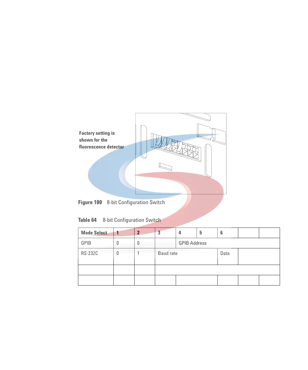
Setting the 8-bit Configuration Switch
The 8-bit configuration switch is located next to the GPIB connector. Switch
settings provide configuration parameters for GPIB address, serial
communication protocol and instrument specific initialization procedures.
Switches 1 and 2 define which set of parameters (for example, for GPIB,
RS-232C, and so on) will be changed. Once the change has been completed, the
instrument must be powered up again in order to store the values in the
non-volatile memory.
Figure 100 8-bit Configuration Switch
Tabl e 64 8-bit Configuration Switch
Mode Select12345678
GPIB 0 0 GPIB Address
RS-232C01Baud rate Data
Bits
Parity
Reserved 1 0 Reserved
TEST/BOOT 1 1 RSVD SYS RSVD RSVD FC
Factory setting is
shown for the
fluorescence detector
 Loading...


