Troubleshooting and Test Functions 4
1100 Series FD Reference Manual 127
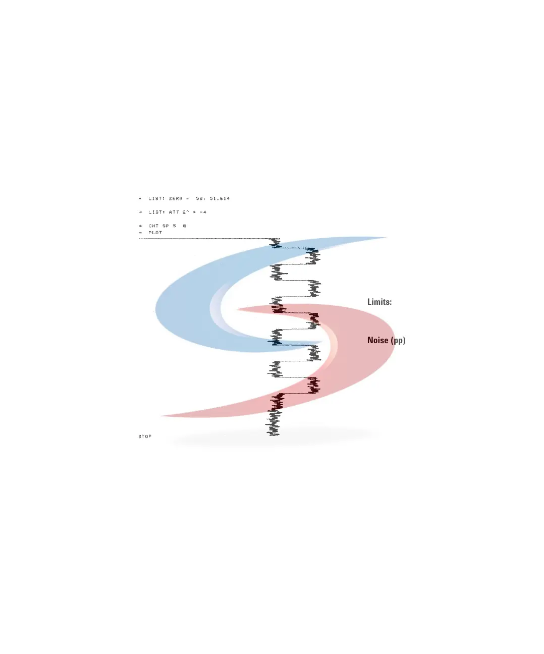
Using the Built-in DAC Test
This function is available from the Control Module ONLY.
The DAC test provides a test pattern as an analog output. The output voltages
(analog 1 and analog 2) should show a constant value corresponding to the
ZERO OFFSET value. In addition to the constant voltage is a switched voltage
with a duration of 12 seconds and a height of 10 µV, see Figure 53.
1 Enable the function (System - Tests - FLD - Enable DAC Test Pattern).
2 Start the plot mode (e.g. Agilent 3396 with ATTN -4, ZERO=50, CS=5).
3 Stop the plot and disable the TAC Test (System - Tests - FLD - Disable DAC
Test Pattern).
4 Evaluate the noise (should be< 5 µV).
Figure 53 DAC Test (Example)
Limits:
Noise (pp) < 5 µV
 Loading...


