Repairing the Fluorescence Detector 5
1100 Series FD Reference Manual 159
Exchanging the Processor Board
1 Turn off the lamp.
2 Switch off the module, and disconnect the cables.
3 Remove module from stack and place it on the workbench.
4 Remove the front cover, top cover and top foam section, see “Removing the
Covers" on page 144.
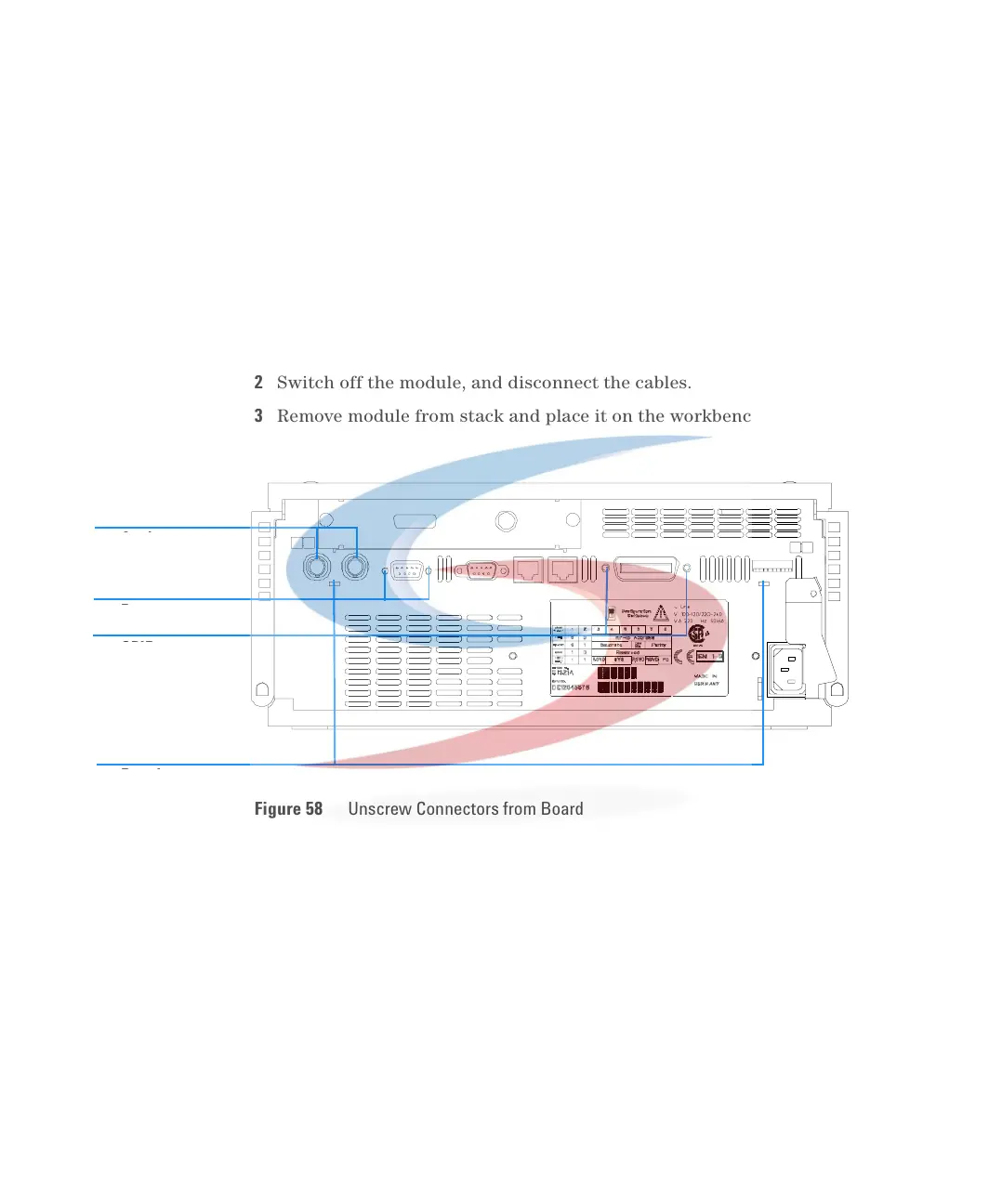
5 Use a 5-mm and 7-mm wrench to unscrew the REMOTE and the GPIB
connector and a 15-mm wrench to unscrew the nuts of the ANALOG
connectors.
6 Disconnect all connectors from the processor board.
When required If detector main board is defective or for repair on other assemblies
Tools re quired Screwdriver POZI 1 PT3
Flat screw driver
Hexagonal wrenches 5 mm, 7 mm and 15 mm
Parts required Detector main board (FLM) G1321-69500 (exchange assembly)
Figure 58 Unscrew Connectors from Board
Remote
GPIB
Analog
connector nuts
Board recesses
Remote
GPIB
Analog
connector nuts
Board recesses
 Loading...


