196 1100 Series FD Reference Manual
5 Repairing the Fluorescence Detector
Replacing the Foams and Covers
Note:
If a new optical unit has been installed or assemblies within the optical unit have been
replaced, then refer “Next Steps” on page 189.
When required When all repairs have been completed
Tools re quired Screwdriver POZI 1 PT3
Prerequisites The detector is open and other procedures have been carried out
NOTE
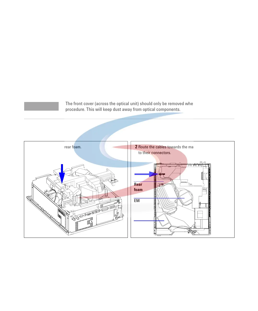
The front cover (across the optical unit) should only be removed when required during a
procedure. This will keep dust away from optical components.
1 Carefully insert the rear foam. 2 Route the cables towards the main board and reconnect
to their connectors.
A
B
A
B
A
EM
EX
Rear
foam
 Loading...


