Theory of Operation 8
1100 Series FD Reference Manual 265
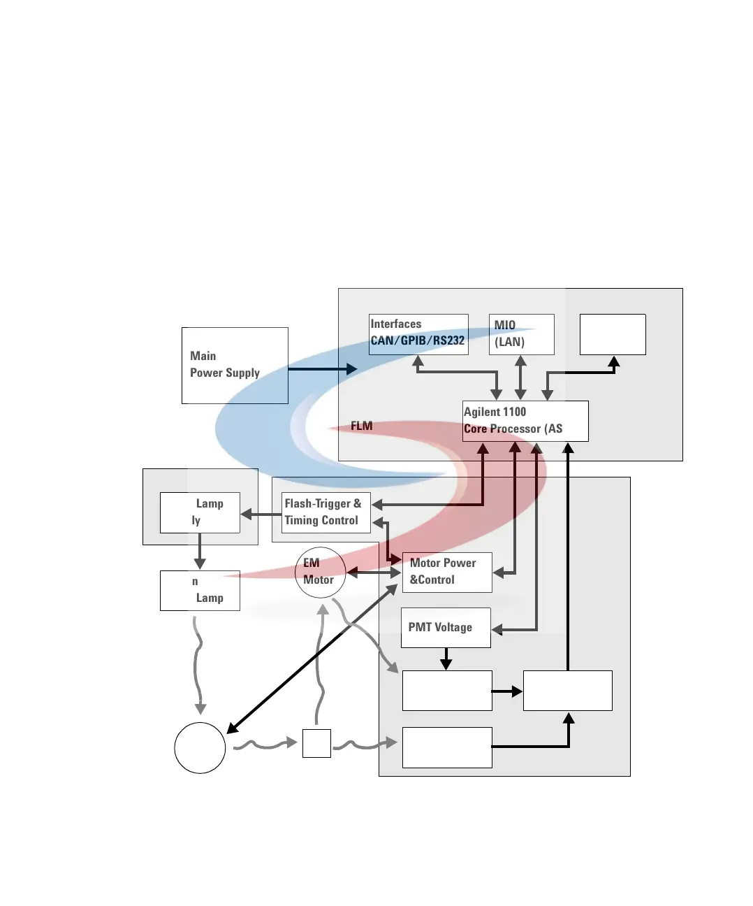
Detector Main Board (FLM)
This board controls all information and activities of all assemblies within the
detector. Through interfaces (CAN, GPIB, RS-232C or LAN) connected to the
user interface, the operator enters parameters, changes modes and controls
the detector.
Figure 90 Detector Electronic Overview
Main
Power Supply
Interfaces
CAN/GPIB/RS232
Analog
Outputs
Agilent 1100
Core Processor (ASIC)
Flash Lamp
Supply
Flash-Trigger &
Timing Control
Xenon
Flash Lamp
EX
Motor
EM
Motor
Motor Power
&Control
PMT Voltage
Photomultiplier
Reference
Diode
Analog
Frontend
FLM
MIO
(LAN)
FLL
FLF
 Loading...


