Repairing the Fluorescence Detector 5
1100 Series FD Reference Manual 187
Replacing the EM and EX Grating
When required If defective
Tools re quired Screwdriver POZI 1 PT3
Hexagonal key, 4 mm and 2.5 mm
Parts required EM Grating assembly G1321-60004 (includes protection ring)
EX Grating assembly G1321-60003 (includes protection ring)
CAUTION
When working on the optical unit, a clean workbench with ESD protection mat must be
available. Otherwise optical components or electronic boards may be damaged.
NOTE
The grating assembly is shipped with a special transport packaging and includes a
protection ring. DO NOT touch the grating surface and DO NOT bend the protection ring.
Preparations for this procedure:
• Optical unit has been removed as described in
“Removing the Optical Unit" on page 178.
• The cables from the position encoders (at the rear of
the EM or EX grating assembly) should be
disconnected.
• Disconnect the encoder cable of the
EX-monochromator from FLF board.
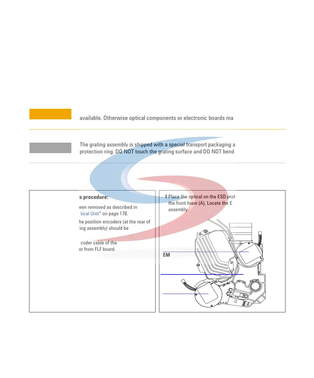
1 Place the optical on the ESD protection mat and remove
the front foam (A). Locate the EM and EX grating
assembly.
A
B
A
B
A
EM
EX
A
 Loading...


