180 1100 Series FD Reference Manual
5 Repairing the Fluorescence Detector
Replacing PMT and/or FLF board
When required If defective or if application specific PMT is required.
Tools re quired Screwdriver POZI 1 PT3
Hexagonal key, 4 mm and 2.5 mm
Tw e e z e r s
Parts required Photo-multiplier Tube (PMT) 1970-0201
Photo-multiplier Tube (PMT) for other application ranges, please contact
Hamamatsu dealers.
Alternative PMTs are either R928HA (185 to 900 nm) or R3788HA (185 to
750 nm). No other PMTs are recommended.
FLF Board G1321-69531 (requires firmware revision A.04.06 or above),
FLR Reference Diode board G1321-66533
CAUTION
When working on the optical unit, a clean workbench with ESD protection mat must be
available. Otherwise optical components or electronic boards may be damaged.
Preparations for this procedure:
• Optical unit has been removed as described in
“Removing the Optical Unit" on page 178.
• The foam must be in place. Otherwise cutoff filter and
diffuser will fall out.
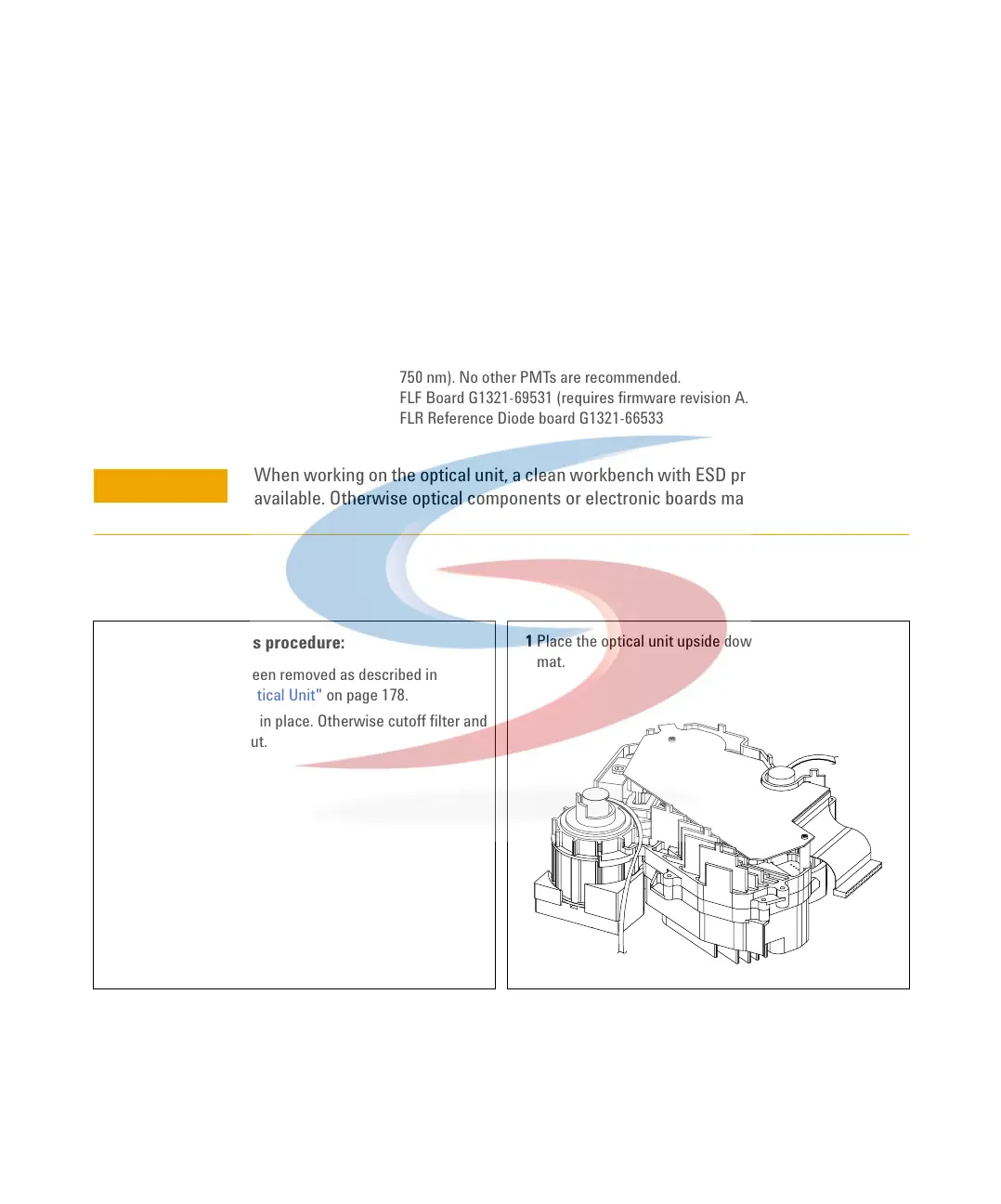
1 Place the optical unit upside down on the ESD protection
mat.
 Loading...


