Theory of Operation 8
1100 Series FD Reference Manual 273
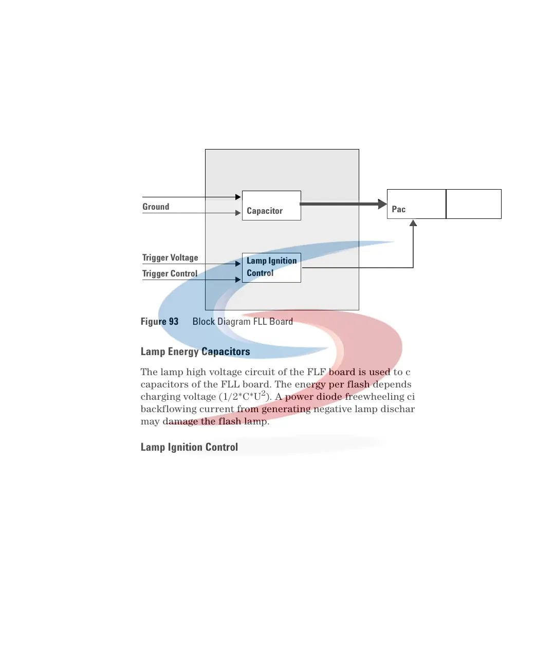
Detector Lamp Supply Board (FLL)
Lamp Energy Capacitors
The lamp high voltage circuit of the FLF board is used to charge the 4 energy
capacitors of the FLL board. The energy per flash depends on the applied
charging voltage (1/2*C*U
2
). A power diode freewheeling circuit prevents the
backflowing current from generating negative lamp discharge currents which
may damage the flash lamp.
Lamp Ignition Control
An ignition voltage is switched by a thyristor to the TriggerPac ignition
transformer to built a small ionized channel (refer “Igniting the Flash
Lamp" on page 270). A freewheeling diode forces the thyristor to switch off
again to prevent lamp damage.
Figure 93 Block Diagram FLL Board
FLL Board
Lamp Voltage
Lamp Energy
Capacitor
Lamp Ignition
Control
Ground
Trigger Voltage
Trigger Control
Tri gg er
Pac
Xenon Flash
Lamp
 Loading...


