178 1100 Series FD Reference Manual
5 Repairing the Fluorescence Detector
Removing the Optical Unit
When required For following repairs: power supply, FLL board, Trigger Pack/FLF board and
PMT.
Tools re quired Screwdriver POZI 1 PT3
Hexagonal key, 4 mm
Parts required Optical unit G1315-69002 (exchange assembly, comes with foam) or
individual parts depending on the following procedures
CAUTION
When working on the optical unit, a clean workbench with ESD protection mat must be
available. Otherwise optical components or electronic boards may be damaged.
NOTE
DO NOT remove the foam from the optical unit unless it is required during a procedure.
Otherwise parts can fall out.
Preparations for this procedure:
• Turn off the detector.
• Disconnect the power cable.
• Disconnect capillaries.
• Remove detector from stack and place it on the
workbench.
• Remove the covers as described in “Removing the
Covers" on page 144.
• Remove the flow cell.
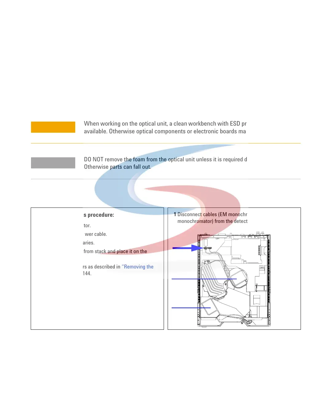
1 Disconnect cables (EM monochromator) and (EX
monochromator) from the detector main board (FLM).
A
B
A
B
A
EM
EX
 Loading...


