288 1100 Series FD Reference Manual
8 Theory of Operation
RS-232C
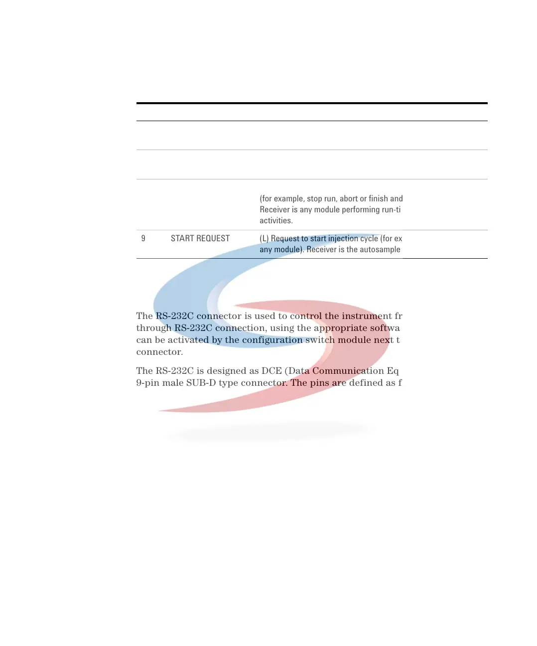
The RS-232C connector is used to control the instrument from a computer
through RS-232C connection, using the appropriate software. This connector
can be activated by the configuration switch module next to the GPIB
connector.
The RS-232C is designed as DCE (Data Communication Equipment) with a
9-pin male SUB-D type connector. The pins are defined as follows:
6 POWER ON (H) All modules connected to system are switched on. Receiver
is any module relying on operation of others.
7 READY (H) System is ready for next analysis. Receiver is any sequence
controller.
8 STOP (L) Request to reach system ready state as soon as possible
(for example, stop run, abort or finish and stop injection).
Receiver is any module performing run-time controlled
activities.
9 START REQUEST (L) Request to start injection cycle (for example, by start key on
any module). Receiver is the autosampler.
Tabl e 62 Remote Signal Distribution (continued)
Pin Signal Description
 Loading...


