160 1100 Series FD Reference Manual
5 Repairing the Fluorescence Detector
7 Remove the processor board. Place the board on the ESD kit.
8 On the new board check the switch setting of address switch S1, see
“Setting the 8-bit Configuration Switch" on page 290.
9 Install the new processor board and reconnect the connectors. Assure that
the board is fitted correctly into the board recess in the rear panel.
10 Refit the screws at the REMOTE and GPIB connectors and the nuts of the
ANALOG connectors.
NOTE
When removing connectors, counter-hold with one hand on connector J12.
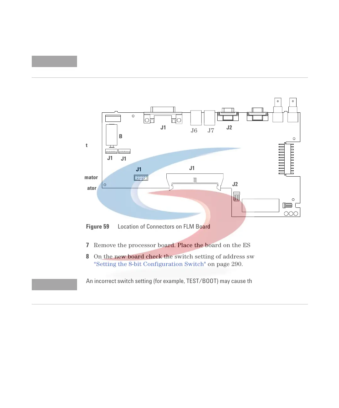
Figure 59 Location of Connectors on FLM Board
J1 - GPIB
J2 - RS-232C
J3 - REMOTE
J4/5 - Analog output
J6/7 - CAN
J11 - Power supply
J12 - EM Monochromator
J14 - EX Monochromator
J17 - NOT USED
J18 - FLF board
J2
J1 J2 J3 J4 J5
J1
B
S1
J1
J1
J1
J1
J2
J2
J6 J7
NOTE
An incorrect switch setting (for example, TEST/BOOT) may cause the module to revert to a
basic mode (yellow or red flashing status light). In this case turn off the module, reset the
address switches, and turn on the module again.
 Loading...


