Introduction to the Fluorescence Detector 7
1100 Series FD Reference Manual 249
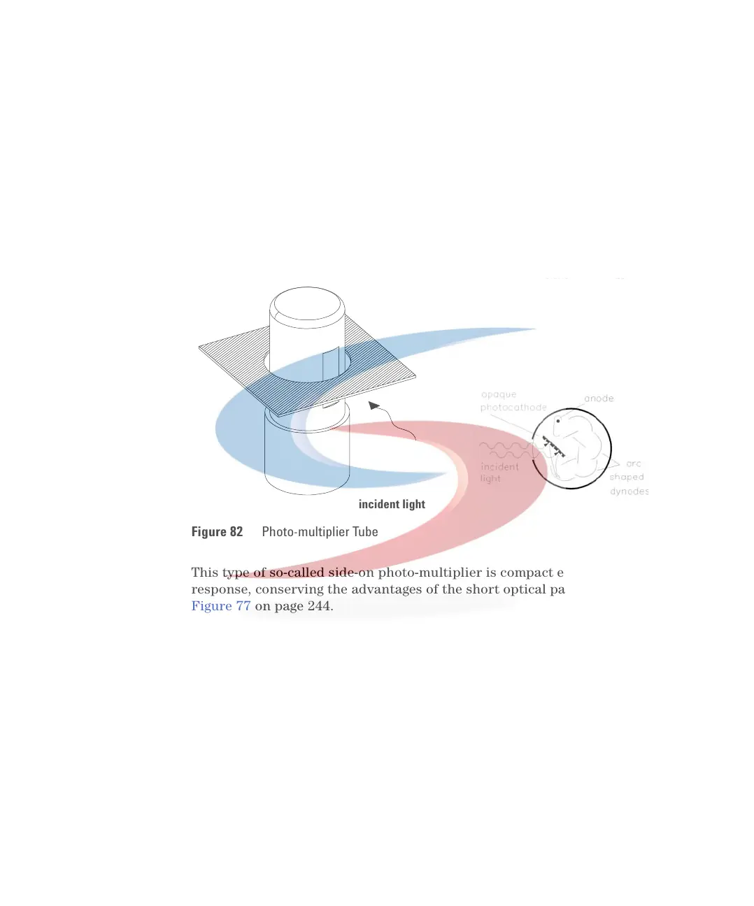
On the photocathode, Figure 82, incident photons generate electrons. These
electrons are accelerated by an electrical field between several arc-shaped
dynodes. Depending on the voltage difference between any pair of dynodes, an
incident electron may spark-off further electrons which accelerate onto the
next dynode. An avalanche effect results: finally so many electrons are
generated that a current can be measured. The amplification is a function of
the voltage at the dynodes and is microprocessor controlled. You can set the
amplification using the PMTGAIN function.
This type of so-called side-on photo-multiplier is compact ensuring fast
response, conserving the advantages of the short optical path shown in
Figure 77 on page 244.
PMTs are designed for specific wavelength ranges. The standard PMT offers
optimum sensitivity from 200 to 600 nm. In the higher wavelength range a
red-sensitive PMT can improve performance. For additional PMT types refer
to“Replacing PMT and/or FLF board" on page 180.
Figure 82 Photo-multiplier Tube
incident light
 Loading...


