Getting Help 1 Getting Started
E6000C Mini-OTDR User’s Guide, E0302
65
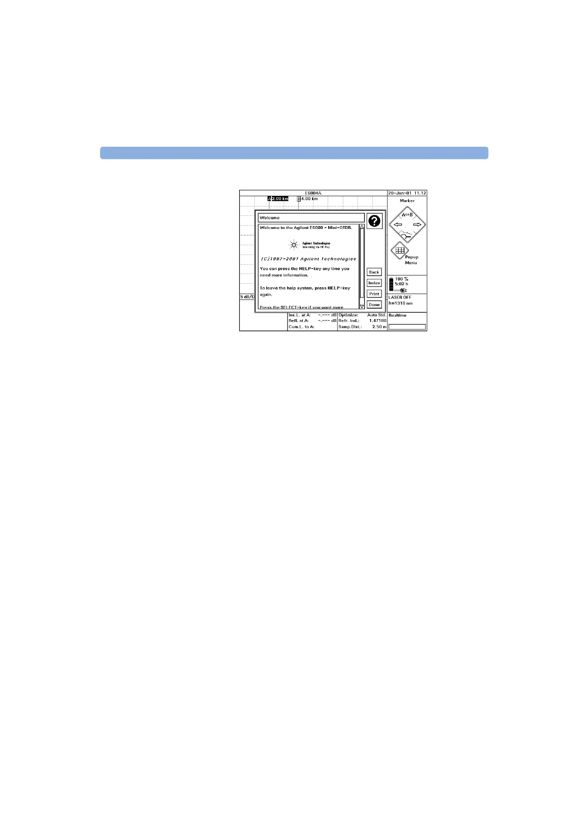
Figure 16 The Mini-OTDR’s Help Display
To leave the online documentation and resume your task,
press the H
ELP key again. Alternatively, cursor right to
Done and press S
ELECT.
Artisan Technology Group - Quality Instrumentation ... Guaranteed | (888) 88-SOURCE | www.artisantg.com