108 of 220 Anatel A643a Alarms - Anatel A643a
RPS - June 2007 - Edition 12
Operator Manual Anatel
When the uncompensated limit is exceeded, an alarm is generated and several things occur:
• The LED corresponding to the Anatel A643a Analyzer’s Channel ID flashes red on all of
its associated C80 Controllers.
• The alarm is logged and becomes available for display on any of those Controllers.
• If the Analyzer is attached to a local or a Gateway printer, a hardcopy of the condition is
generated containing the time of the excursion, the measured conductivity and
temperature, and the USP conductivity limit exceeded. For example:
12:07 Alarm 1.45 µS @ 33.2C >[1.4 @ 30C]
Excursions reported in subsequent analyses are output only at the normal user-specified
interval (or in response to a percent change in the readings) unless the sample water
conductivity falls below the specified limit. In that case, a new alarm report is output to
ensure that each limit excursion is recorded.
• The Sensor’s Digital Output #2 is asserted to allow alarm annunciation to an external
device (see “Hardware Setup” on page 143).
7.4 Alarm Acknowledgement
A limit excursion is acknowledged by specifying the errant Analyzer and then pressing the
Alarm Key. Acknowledgement stops the Controller’s LCD from flashing, stops the flashing red
Channel ID, and silences the audible warning. If more than one alarm has been detected, all
must be acknowledged before these fault indications are terminated. The red Channel LED is
restored to green when the Analyzer’s TOC level falls below its set limit.
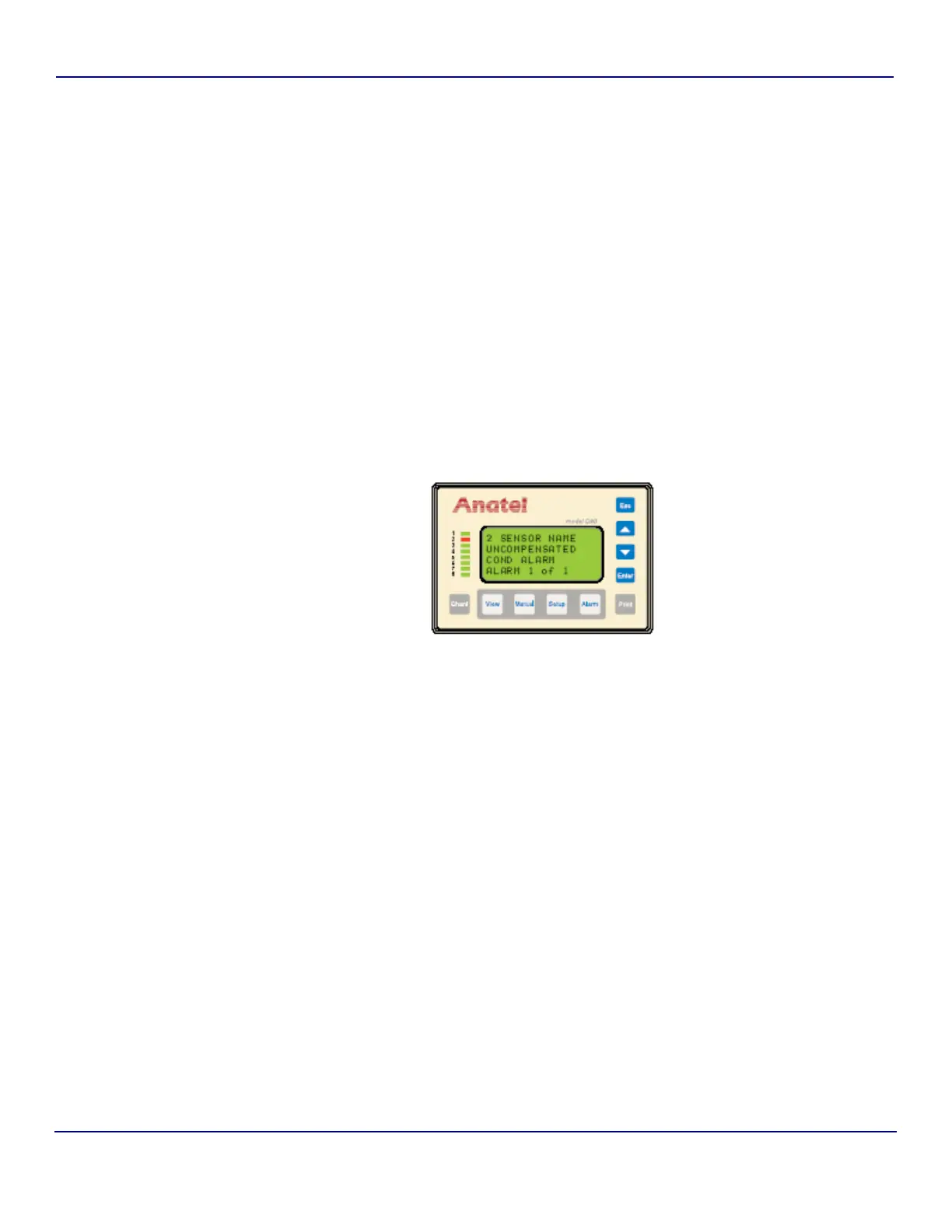
Acknowledgement presents the following alarm information on the Controller’s LCD display:
Fig 7-16 : Uncompensated Conductivity Alarm
Line 1 The affected instrument’s Channel ID and its userentered Name.
Line 2 The cause of the alarm.
Line 3 The date and time the alarm was detected.
Line 4 The current number of alarms logged for the displayed Analyzer.