Anatel A643a - Digital Inputs & Outputs 141 of 220
RPS - June 2007 - Edition 12
Anatel Operator Manual
10.2.2 Software Setup
The Digital Control parameter must be enabled for the Anatel A643a to accept any digital
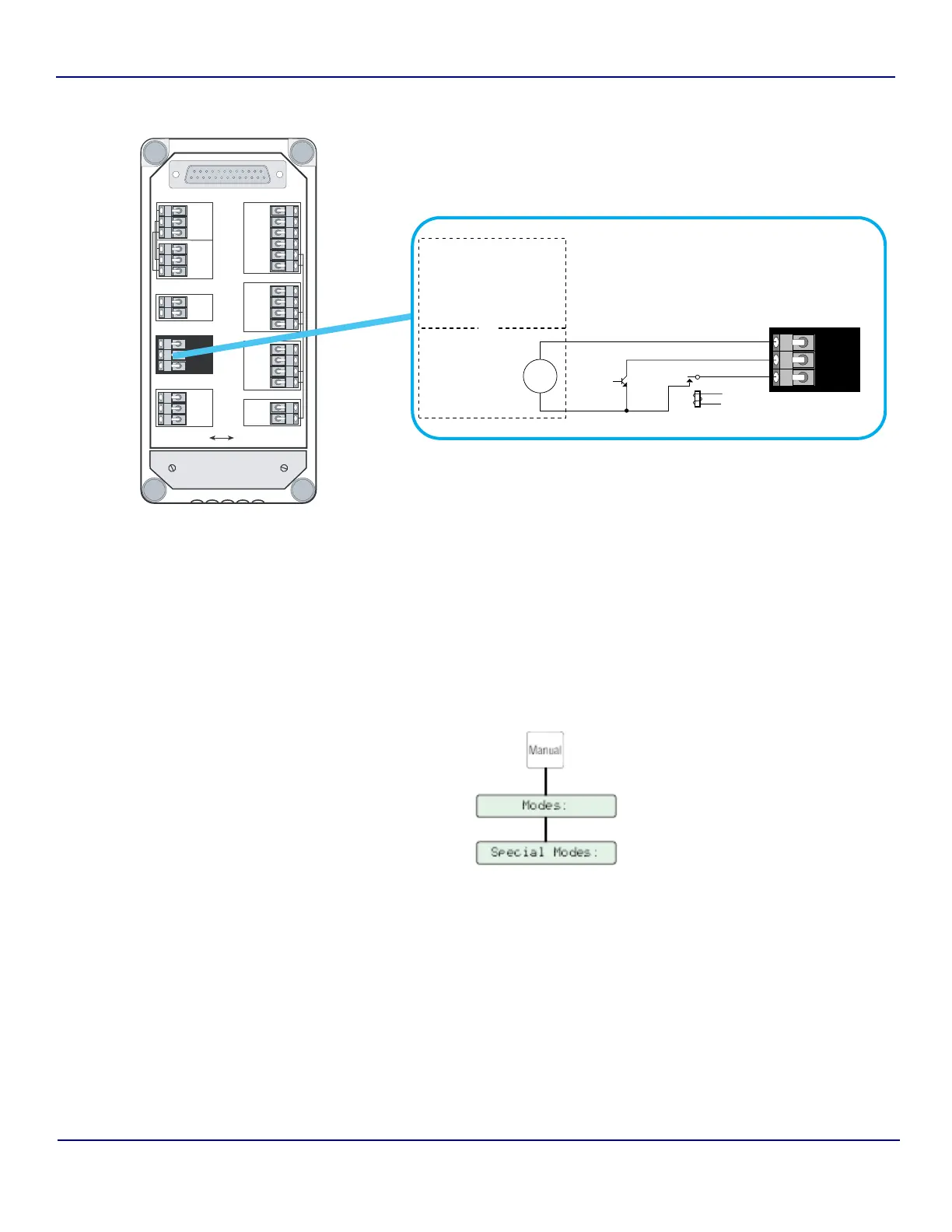
input signals. This software switch is accessed through the Manual Key and, once enabled,
displays r/c in conjunction with the Analyzer’s displayed TOC readings to indicate that the
instrument is operating under remote control.
To enable external Digital Control:
1) With the desired Analyzer selected in any View, press the Manual Key to display its
submenu.
Fig 10-1 : Typical Digital Input Wiring
TxD1
RxD1
RTS1
CTS1
SG
PG
TxD2
RxD2
SG
PG
TxD3
RxD3
SG
PG
Isolated
DATA ACQUISITIONPRINTERDIAGNOSTICS
BIAS
Non-Isolated
OUTPUTS
INPUTS
4-20mA
NET+
NET
COM
NET AUX
NET+
NET
COM
OUT1*
OUT2*
COM
COM+
IN1*
IN2*
+12V
COM
OUT+
OUT
Strain Relief
Plate
COM+
IN1*
IN2*
NPN
Open
Collector
Driver
Relay
Driver
+
External Power Source Range:
5 VDC min. @ 1 mA
30 VDC max. @ 10 mA
INPUTS
Access 643
Connector Block
Analyzer Internal
Bias Port
+12 V,
Common ()
or
User -Supplied
530 VDC
Power
Source
Fig 10-2 : Software Setup