Anatel A643a - Network Installation 41 of 220
RPS - June 2007 - Edition 12
Anatel Operator Manual
To change the Controller’s A-Net address:
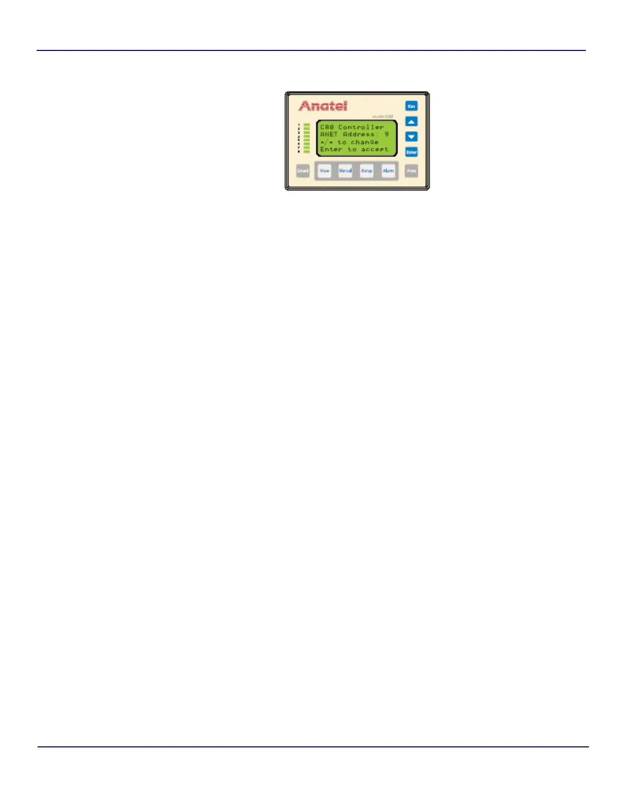
1) While holding the Setup Key down, cycle the Controller’s power by removing, then
restoring, its power connection (on an A643aS or A643aP, simply turn the Sensor OFF
and then back ON). The Controller displays its current address.
2) Use the Up and Down Keys in order to scroll the Controller’s A-Net Address to the
desired setting (9–16).
3) Press Enter to retain the displayed setting and return to normal operation.
3.3 Network Setup
The A-Net Network is configured by making the necessary communications connections
between multiple Sensors and their managing Controller(s) using the shielded twin-axial
cabling. The cable’s BNC twist-lock fittings allow quick and easy connection and disconnection
of any component without disrupting overall Network operation.
The A-Net Network must be configured as a single trunk line with each component connected
through an individual tee connector using a local cable no longer than 3 feet. The A-Net trunk
line can extend a total of 3000 feet not including these local cable lengths. If the trunk line
exceeds 500 feet, its cable should be installed in conduit which is free from other cables or AC
buses to prevent the potential for electrical interference.
To establish A-Net communications:
1) Grasp the end of the 3-foot local cable attached to a C80 Controller and, noting the
alignment of its internal pins, gently push it onto the middle coupling of the tee
connector. Twist the cable onto the connector until it “locks” on the coupling.
2) Similarly fasten the local cable that extends from the other network components to their
respective tee connectors.
3) Link the various tee connectors using sections of twin-axial trunk cable.
4) Both ends of the Network must be terminated to control noise and help ensure a clean
signal. The passive terminators (P/N FG 2005901) provided with each system
component should be fastened to the open jack connector at each end of the A-Net
Network with a total trunk length less than 500 feet.
Fig 3-4 : Controller Address Screen