Anatel A643a - Network Installation 43 of 220
RPS - June 2007 - Edition 12
Anatel Operator Manual
3.3.1 Network Connections
The local cable must be attached to an analyzer when connecting it to the network. This 3-foot
communications cable is provided with each portable Sensor and can be found in its
installation kit.
The stationary A643a-S Analyzer is shipped with the local cable already installed.
Always disconnect the instrument from its power source before attempting to access internal
components.
Network connections are made to the NET Port on the Sensor’s I/O Connector Block as
follows:
1) Turn the Sensor OFF and disconnect the power cord from its source.
2) Remove the I/O Connector Block from the bottom of the Sensor by loosening the four
thumbscrews.
3) Loosen and remove the two Phillips-head screws that secure the metal strain relief
plate.
4) Feed the interface wiring through one of the five holes at the end of the Connector
Block cover and along the corresponding slot in the foam padding.
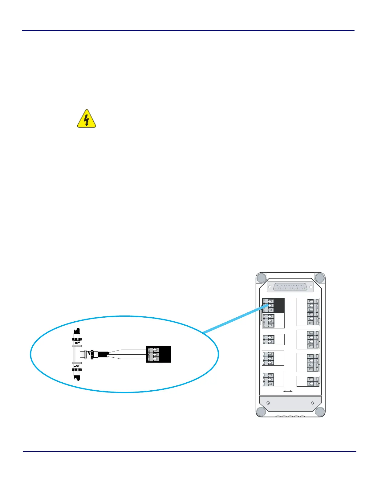
5) Make the necessary connections to the Sensor’s NET port as shown.
Fig 3-6 : Sensor NET Port Connections
TxD3
RxD3
SG
PG
Isolated
DATAACQUISITIONPRINTERDIAGNOSTICS
BIAS
Non-Isolated
OUTPUTS
INPUTS
4-20mA
NET AUX
OUT1*
OUT2*
COM–
COM+
IN1*
IN2*
+12V
COM
OUT+
OUT–
TxD1
RxD1
RTS1
CTS1
SG
PG
NET+
NET–
COM
NET+
NET–
COM
TxD2
RxD2
SG
PG
Strain Relief
Plate
NET+
NET–
COM
White
Blue
Shield
NET
Access 643
Connector Block
Anatel A643a
Connector Block