130 of 220 Analog Outputs - Anatel A643a
RPS - June 2007 - Edition 12
Operator Manual Anatel
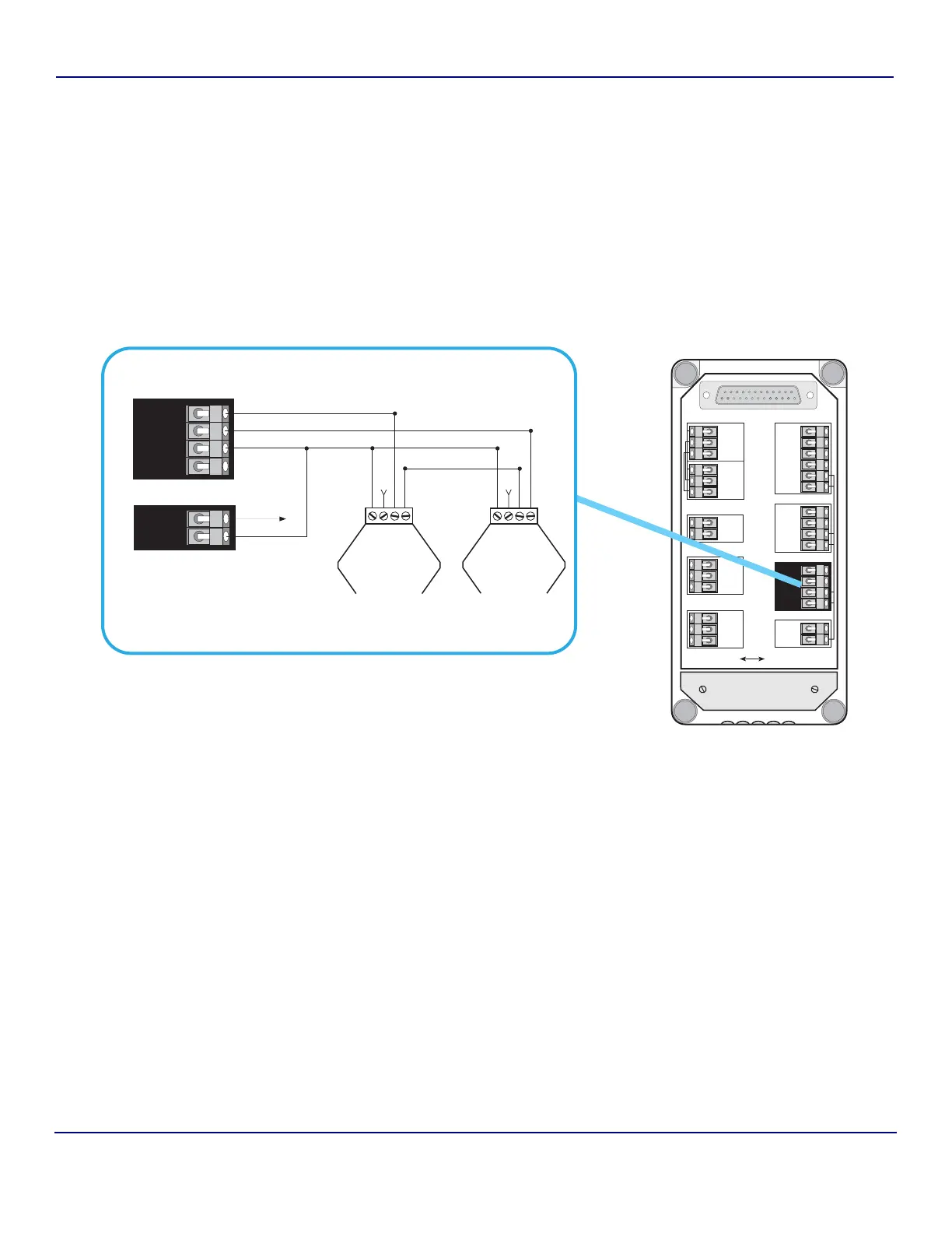
These auxiliary analog connections are made on the Analyzer’s I/O Connector Block as
follows:
1) Turn the Anatel A643a Analyzer OFF and disconnect the power cord from its source.
2) Remove the I/O Connector Block from the bottom of the Analyzer by loosening its four
screws.
3) Loosen and remove the two screws that secure the metal strain relief plate.
4) Feed the Module wiring through one of the five holes at the end of the Connector Block
cover and along the corresponding slot in the foam padding.
5) Make the necessary connections to the Analyzer’s DIAGNOSTICS port as shown.
The Access 643P Analyzer’s integral printer is wired to its BIAS port. An external +12 VDC
supply must be provided for any DAC Modules used with these instruments.
6) Replace the metal strain relief plate.
7) Replace the I/O Connector Block on the bottom of the Analyzer, taking care not to pinch
any wires, and secure it in place by tightening the screws.
8) Reconnect the power cord and turn the Sensor ON.
Fig 9-18 : External DAC Wiring
Isolated
DATAACQUISITIONPRINTERDIAGNOSTICSBIAS
Non-Isolated
OUTPUTS
INPUTS
4-20mA
NET+
NET–
COM
NET AUX
NET+
NET–
COM
OUT1*
OUT2*
COM–
COM+
IN1*
IN2*
+12V
COM
OUT+
OUT–
TxD1
RxD1
RTS1
CTS1
SG
PG
TxD2
RxD2
SG
PG
TxD3
RxD3
SG
PG
Strain Relief
Plate
TxD3
RxD3
SG
PG
DIAGNOSTICS
BIAS
TRANSMIT
RECEIVE
+VS
GND
TRANSMIT
RECEIVE
+VS
GND
External
Resistivity
DAC Module
(FG 2006701)
External
Temperature
DAC Module
(FG 2006801)
+12V
COM
To +Vs
Gnd
A643
Connector Block