Anatel A643a - Instrument Installation 37 of 220
RPS - June 2007 - Edition 12
Anatel Operator Manual
The Controller reports if it is unable to establish communications with the Analyzer
and suggests checking the wiring connections. Once the Controller has established
communications, any other faults detected during the power-up diagnostics may be examined
by pressing the Alarm Key. Summaries of any problems encountered are displayed and output
to the printer (refer to “Alarm Codes” on page 175 for information on reported Alarm Codes and
their possible indications). When its self-diagnostics have been completed successfully,
sample flow begins and the Analyzer initiates an automatic analysis cycle based on factory
default parameters. If there is no flow through the instrument, check the isolation valve and the
Flow Adjust control (see step 7 below).
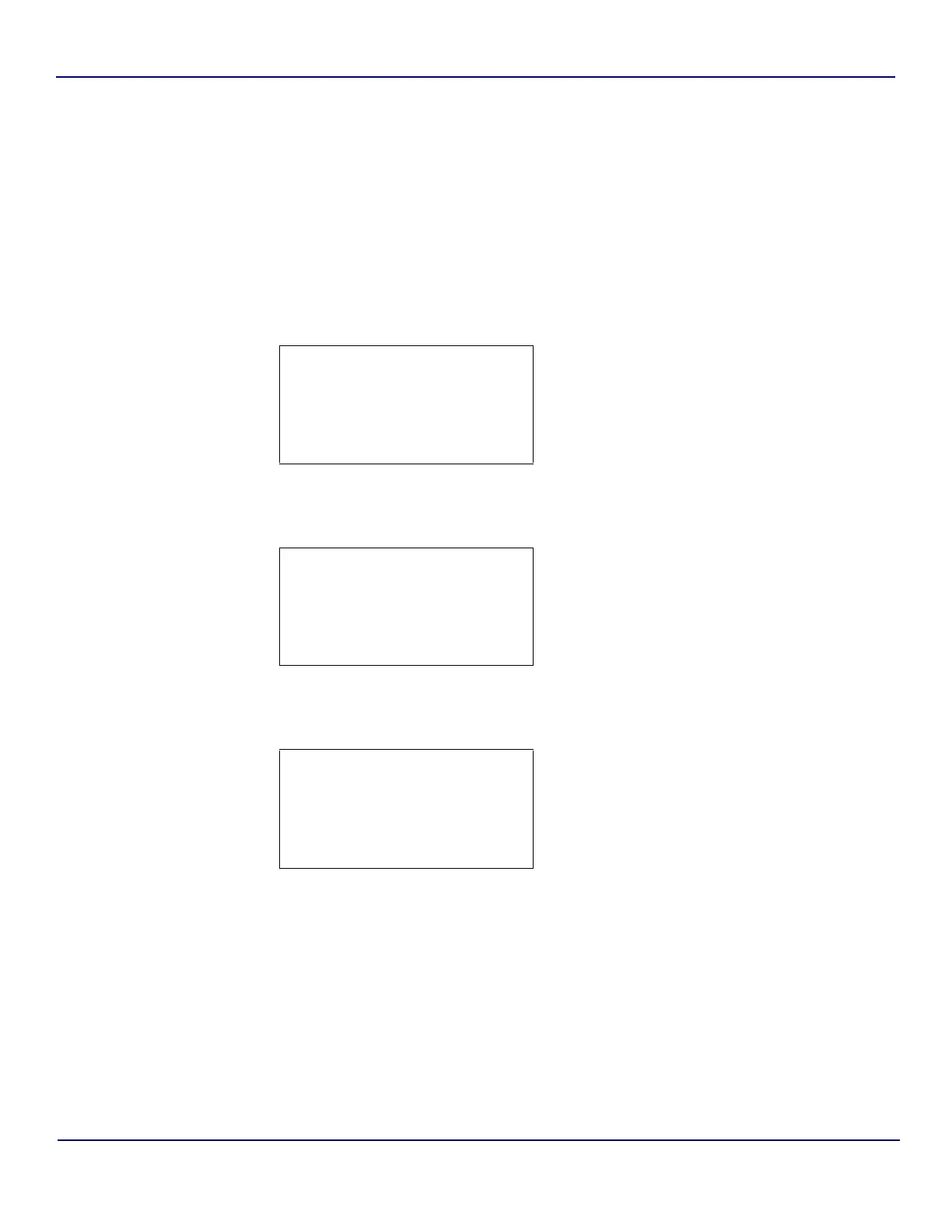
3) Press the Manual Key in order to access the Analyzer’s Manual Menu.
4) Select Modes, then press Enter to access its submenu.
5) Specify Special Modes and press Enter to display the available options.
6) Use the Up and Down Keys to specify Clean.
7) Press Enter to place the Anatel A643a in its Self-Clean Mode of operation, then press
Esc twice to return to the normal display.
CLEAN MODE is displayed on the Controller’s LCD for the Anatel A643a. In this
mode, the Analyzer’s UV lamp is turned on to oxidize any contaminants inside its
measurement cell and sample water flows through the instrument to flush away
impurities. Allow the Analyzer to run in this state for 3 to 4 hours, longer if the sample
tube is lengthy or if the sample point is at low pressure, such as a gravity-feed tube.
Monitor the drain tube to verify that there is a sample flow of at least 60 mL/minute. The
sample flow rate is increased or decreased by turning the Flow Adjust knob located on
1 SENSOR NAME
X Modes
Manual Samples:
Calibrations:
Fig 2-25 : Manual Menu
1 SENSOR NAME
Auto TOC
Purge
X
Special Modes
Fig 2-26 : Modes Menu
1 SENSOR NAME
X Clean
Digital Contrl:
Fig 2-27 : Special Modes Menu