Anatel A643a - Anatel A643a Maintenance 169 of 220
RPS - June 2007 - Edition 12
Anatel Operator Manual
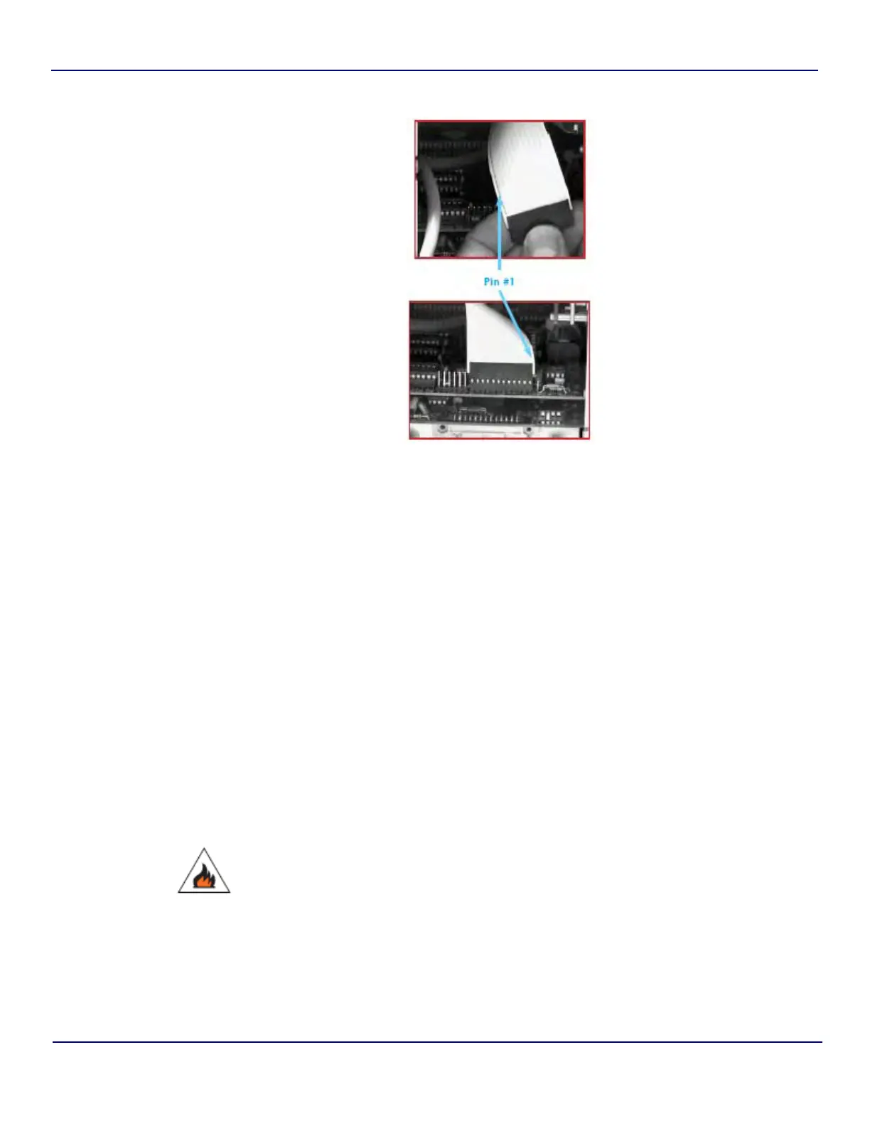
11) Position the DC power cable on the right side of the flexible ribbon cable before
reconnecting it to the processor board. For Access 643P Analyzers, the connector is
the leftmost set of pins at the end of the processor board; for Anatel A643a Analyzers,
it is the rightmost set of pins. In either case, the black dotted line (indicating Pin #1) on
the ribbon cable should be on the right side.
12) Tuck the DC power cable in front of the flexible cable to prevent it from contacting
exposed blades of the fan assembly and replace the Electronics Cover. Make sure the
DC cable is not pinched between the power supply and the circuit boards.
13) Restore AC power to the Sensor. The Controller initially will report Code 10 and
Code 11: Check Battery when the Analyzer is first turned ON. This display is normal
and should be ignored.
14) Referring to the printout and “Anatel A643a Setup” on page 51, restore any parameter
settings that differ from the factory defaults, including the access password if one was
specified.
15) Set the Analyzer’s internal clock as described in “System Time” on page 22.
16) Recalibrate the instrument as described in “TOC Calibration” on page 82.
Properly dispose of expired batteries. Lithium batteries present a fire, explosion and burn
hazard—do not attempt to incinerate, recharge or disassemble them.
Fig 13-19 : Pin #1