Anatel A643a - Analog Outputs 131 of 220
RPS - June 2007 - Edition 12
Anatel Operator Manual
9.3.2 Software Setup
The output signal generated at the conclusion of an analysis cycle is calculated based on the
sample’s reading and represents either conductivity (in µS/cm), resistivity (in M.-cm) or
temperature (in °C). The transmitted signal remains constant until the next analysis cycle is
complete. If a critical alarm is encountered during an analysis, the external analog output goes
to a pre-defined output state.
Setting the External DAC output consists of:
1) 1. Enabling the Analyzer’s DAC output.
2) Specifying the analog output range.
3) Defining the associated zero-scale and full-scale values that establish the resolution of
that signal.
4) Establishing the signal that is to be output in the event of an Anatel A643a alarm.
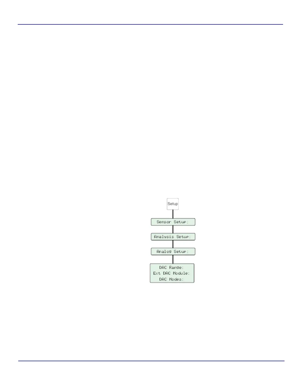
9.3.2.1 External DAC Module
Default: No
This software switch enables and disables the conductivity (or resistivity) and temperature
output to an External DAC Module. The Module then converts the output into an analog signal
for processing by a variety of devices. This signal also reflects the DAC Error Output (see
“DAC Error Output” on page 128) in the event of an Anatel A643a alarm.
Fig 9-19 : External DAC Module Setup