122 of 220 Analog Outputs - Anatel A643a
RPS - June 2007 - Edition 12
Operator Manual Anatel
Always disconnect the instrument from its power source before attempting to access internal
components.
1) Turn the Anatel A643a Analyzer OFF and disconnect the power cord from its source.
2) Remove the I/O Connector Block from the bottom of the Analyzer by loosening its four
screws.
3) Loosen and remove the two screws that secure the metal strain relief.
4) Feed the interface wiring through one of the five holes at the end of the Connector
Block cover and along the corresponding slot in the foam padding.
5) Make the necessary positive and ground connections to the Analyzer’s 4-20mA
terminals.
6) Replace the metal strain relief plate.
7) Replace the I/O Connector Block on the bottom of the Analyzer, taking care not to pinch
any wires, and secure it in place by tightening the screws.
8) Reconnect power and turn the Analyzer ON.
The I/O Connector Block must be reinstalled correctly to conform to emissions specifications.
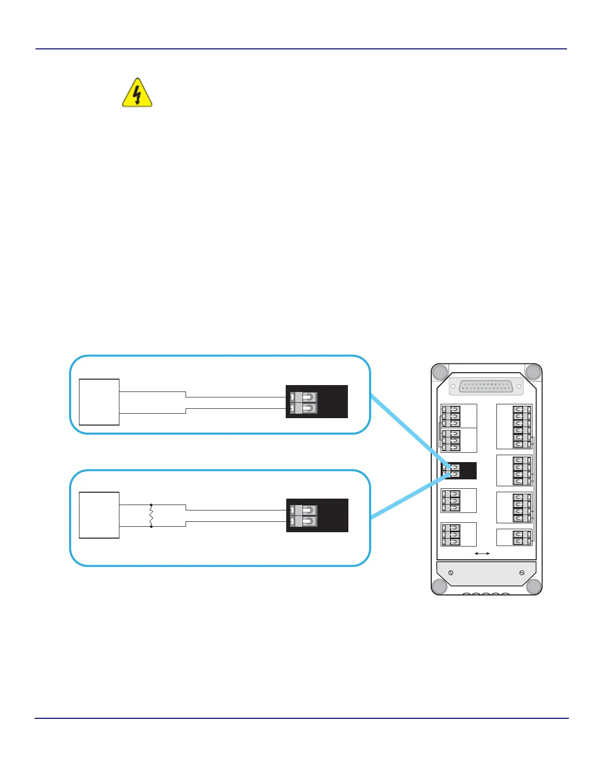
Fig 9-1 : Current and Voltage Output Wiring
Isolated
DATAACQUISITIONPRINTERDIAGNOSTICSBIAS
Non-Isolated
OUTPUTS
INPUTS
4-20mA
NET+
NET–
COM
NET AUX
NET+
NET–
COM
OUT1*
OUT2*
COM–
COM+
IN1*
IN2*
+12V
COM
OUT+
OUT–
TxD1
RxD1
RTS1
CTS1
SG
PG
TxD2
RxD2
SG
PG
TxD3
RxD3
SG
PG
Strain Relief
Plate
CURRENT OUTPUT WIRING
VOLTAGE OUTPUT WIRING
OUT+
OUT–
Data
Acquisition
System
(user-supplied)
+
–
4–20mA
A643
Connector Block
OUT+
OUT–
Data
Acquisition
System
(user-supplied)
50-500 ohm
Wirewound
Precision
Resistor
Conversion Resistor
(user-supplied)
+
–
4–20mA
A643
Connector Block