60 of 220 Anatel A643a Setup - Anatel A643a
RPS - June 2007 - Edition 12
Operator Manual Anatel
the resulting change in conductivity is used to calculate the concentration of Total Organic
Carbon present in parts per billion (ppb).
The Auto TOC analysis process is comprised of three successive stages: the Sample,
Oxidation and Idle Times. These intervals are referred to collectively as the Cycle Time,
its duration specified in the Analyzer’s setup (see “Cycle Time” on page 65).
During the Sample Time interval, the UV lamp is turned off and the Analyzer’s internal
Sample Valve 2 is opened to allow pressurized water from the Process Water Inlet to purge the
measurement cell. Sample Valve 2 is closed at the conclusion of the Sample Time to capture
a new sample in the cell. The conductivity and the temperature of the sample water are
measured to establish reference values which are stored in the instrument’s memory for use
in calculating the TOC results.
During the Oxidation Time, the Analyzer’s Sample Valve 2 remains closed, the UV lamp is
turned on and oxidation begins. This interval varies depending on the organic content of the
water. The nature of the oxidation curve determines the sample to be one of the following
Profile Types:
Conductivity is always increasing until oxidation is complete in a P1 sample. This indicates that
few intermediate organic acids, which have higher conductivity than the equivalent CO
2
, are
formed. A P3 sample contains significant amounts of these acids. Consequently, conductivity
peaks then decreases as analysis nears completion. P2 samples occur at low TOC levels and
are similar to a P1, or minor P3, sample in which the organic “background” of the measurement
cell must be measured.
Fig 5-15 : Analysis Time Line
Profile Type 1 (“P1”) Easy to oxidize
Profile Type 2 (“P2”) Moderately difficult to oxidize (only in TOC levels below 25 ppb)
Profile Type 3 (“P3”) Difficult to oxidize (intermediate organic acids are formed)
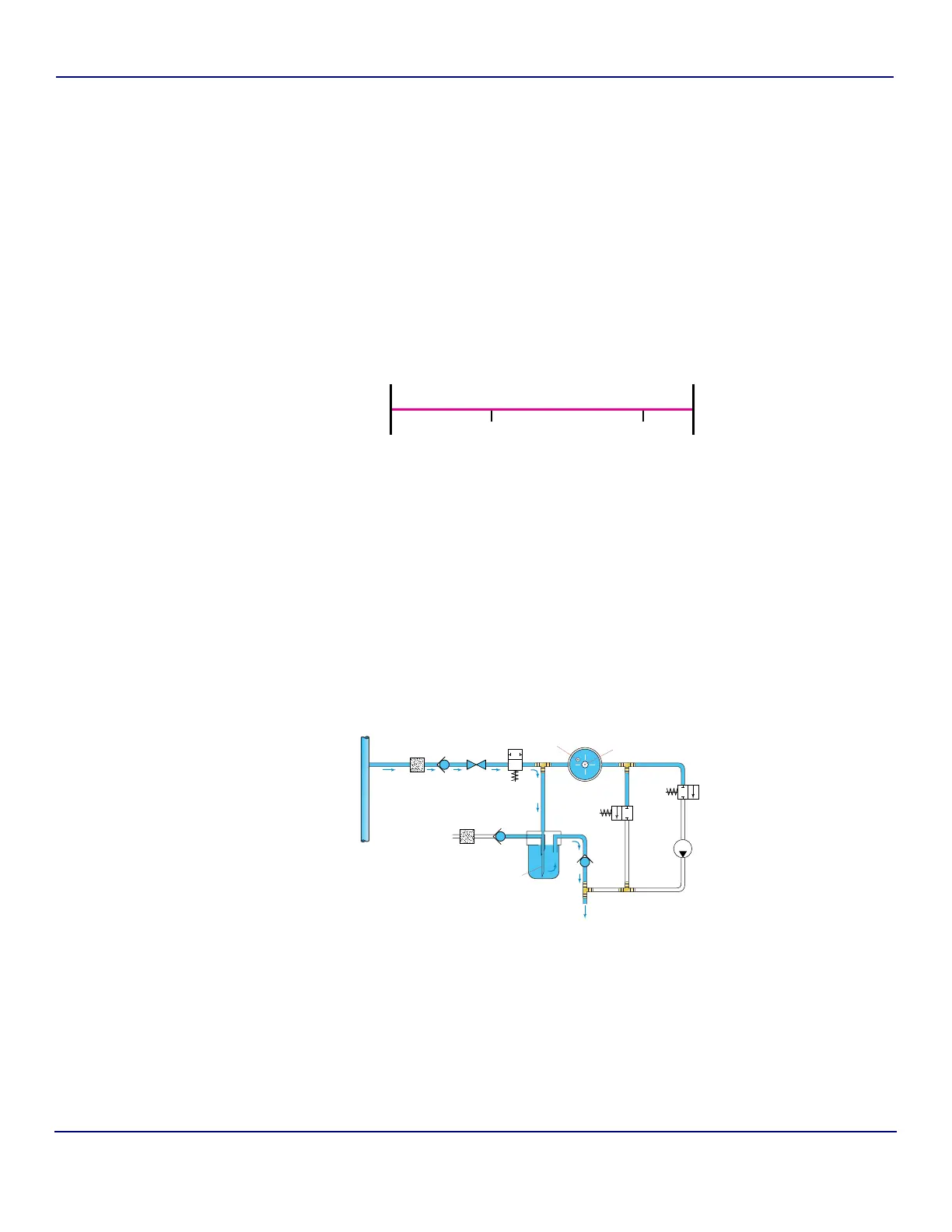
Fig 5-16 : Oxidation State
Sample Time
Oxidation Time Idle Time
(if present)
Cycle Time
Check
Valve
Needle
Valve
Check
Valve
15 Micron
Filter
Bypass
Check
Valve
Sample
Valve 1
Sample
Vessel
Pump
Sample
Valve 2
Calibration
Valve
Analysis
Cell
Thermistor
UV Lamp
Sample
Needle
Drain
Process
Water
Inlet
Air
Filter
Air Inlet
Oxidation
State
Note: Arrows indicate flow path.