S331L UG PN: 10580-00321 Rev. M 12-7
Video Inspection Probe (VIP) 12-4 Operation
4. Optionally, use the rotary knob and arrow keys to zoom and pan
the image, respectively. The Zoom Control Help key displays the
related Help message.
5. To execute the VIP image analysis, press the Analyze submenu
key. Skip this step if the Auto Analyze setting is On, in which
case the image is automatically analyzed when captured (refer to
the “Setup Menu” on page 12-12).
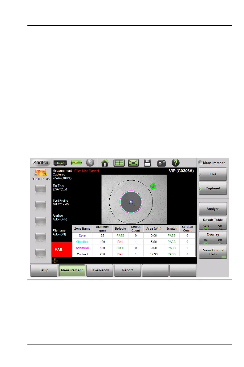
After the analysis completes, the overall Pass/Fail indicator is
displayed in the lower left corner of the screen.
6. Press the Results Table submenu key to show or hide the detailed
analysis results. See Figure 12-6. For each of the analysis areas,
or zones (core, cladding, adhesive, contact), the table shows the
count of scratches and contaminations or defects, and their
Pass/Fail evaluation results. The table will not appear if there are
no analysis results to display.
7. Press the Overlay submenu key to turn on and off the colored
circles around the analysis areas, and the red and green
highlights showing the defects and scratches found on the
connector endface. Defects of an acceptable size are green (Pass).
Defects that are large enough to potentially cause a problem are
highlighted in red (Fail).
Figure 12-6. VIP Image Captured and Analyzed