158
8331B–AVR–03/12
Atmel AVR XMEGA AU
• Bit 2:0 – ISC[2:0]: Input/Sense Configuration
These bits set the input and sense configuration on pin n according to Table 13-6. The sense
configuration decides how the pin can trigger port interrupts and events. If the input buffer is not
disabled, the input cannot be read in the IN register.
Note: 1. A low-level pin value will not generate events, and a high-level pin value will continuously gen-
erate events.
2. Only PORTA - PORTF support the input buffer disable option. If the pin is used for analog func-
tionality, such as AC or ADC, it is recommended to configure the pin to INPUT_DISABLE.
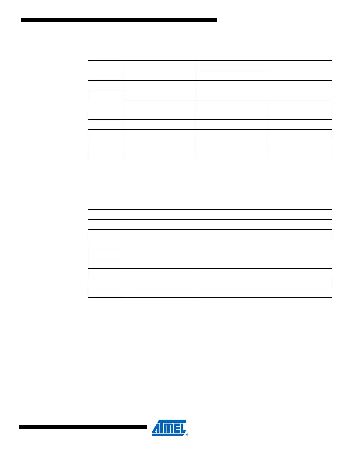
Table 13-5. Output/pull configuration.
OPC[2:0] Group Configuration
Description
Output Configuration Pull Configuration
000 TOTEM Totem-pole (N/A)
001 BUSKEEPER Totem-pole Bus-keeper
010 PULLDOWN Totem-pole Pull-down (on input)
011 PULLUP Totem-pole Pull-up (on input)
100 WIREDOR Wired-OR (N/A)
101 WIREDAND Wired-AND (N/A)
110 WIREDORPULL Wired-OR Pull-down
111 WIREDANDPULL Wired-AND Pull-up
Table 13-6. Input/sense configuration.
ISC[2:0] Group Configuration Description
000 BOTHEDGES Sense both edges
001 RISING Sense rising edge
010 FALLING Sense falling edge
011 LEVEL Sense low level
(1)
100 Reserved
101 Reserved
110 Reserved
111 INTPUT_DISABLE Digital input buffer disabled
(2)

 Loading...


