200
8331B–AVR–03/12
Atmel AVR XMEGA AU
15.10.3 CTRLC – Control register C
• Bit 7:0 – HCMPx/LCMPx: High/Low Compare x Output Value
These bits allow direct access to the waveform generator's output compare value when the
timer/counter is OFF. This is used to set or clear the WG output value when the timer/counter is
not running.
15.10.4 CTRLE – Control register E
• Bit 7:2 – Reserved
These bits are unused and reserved for future use. For compatibility with future devices, always
write these bits to zero when this register is written.
• Bit 1:0 – BYTEM[1:0]: Byte Mode
These bits select the timer/counter operation mode according to Table 15-3 on page 200.
15.10.5 INTCTRLA – Interrupt Enable register A
• Bit 7:4 – Reserved
These bits are unused and reserved for future use. For compatibility with future devices, always
write these bits to zero when this register is written.
Bit 76543210
+0x02 HCMPD HCMPC HCMPB HCMPA LCMPD LCMPC LCMPB LCMPA CTRLC
Read/Write R/W R/W R/W R/W R/W R/W R/W R/W
Initial Value00000000
Bit 76543210
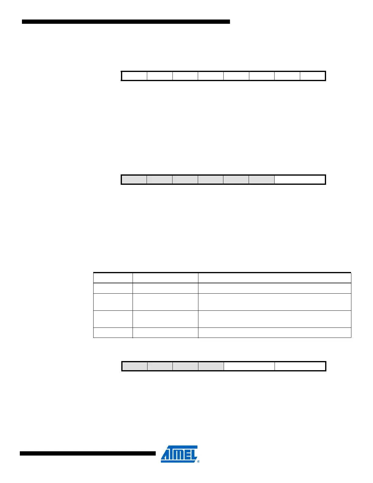
+0x04 – – – – – – BYTEM[1:0] CTRLE
Read/Write R R R R R R R/W R/W
Initial Value00000000
Table 15-3. Byte Mode
BYTEM[1:0] Group Configuration Description
00 NORMAL Timer/counter is set to normal mode (timer/counter type 0)
01 BYTEMODE
Upper byte of the counter (HCNT) will be set to zero after
each counter clock.
10 SPLITMODE
Timer/counter is split into two eight-bit timer/counters
(timer/counter type 2)
11 — Reserved
Bit 76543210
+0x06 – – – – HUNFINTLVL[1:0] LUNFINTLVL[1:0] INTCTRLA
Read/WriteRRRRR/WR/WR/WR/W
Initial Value00000000

 Loading...


