201
8331B–AVR–03/12
Atmel AVR XMEGA AU
• Bit 3:2 – HUNFINTLVL[1:0]: High-byte Timer Underflow Interrupt Level
These bits enable the high-byte timer underflow interrupt and select the interrupt level, as
described in ”Interrupts and Programmable Multilevel Interrupt Controller” on page 134. The
enabled interrupt will be triggered when HUNFIF in the INTFLAGS register is set.
• Bit 1:0 – LUNFINTLVL[1:0]: Low-byte Timer Underflow Interrupt Level
These bits enable the low-byte timer underflow interrupt and select the interrupt level, as
described in ”Interrupts and Programmable Multilevel Interrupt Controller” on page 134. The
enabled interrupt will be triggered when LUNFIF in the INTFLAGS register is set.
15.10.6 INTCTRLB – Interrupt Enable register B
• Bit 7:0 – LCMPxINTLVL[1:0]: Low-byte Compare x Interrupt Level
These bits enable the low-byte timer compare interrupt and select the interrupt level, as
described in ”Interrupts and Programmable Multilevel Interrupt Controller” on page 134. The
enabled interrupt will be triggered when LCMPxIF in the INTFLAGS register is set.
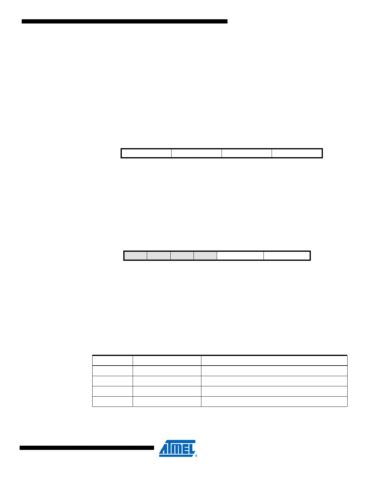
15.10.7 CTRLF – Control register F
• Bit 7:4 – Reserved
These bits are unused and reserved for future use. For compatibility with future devices, always
write these bits to zero when this register is written.
• Bit 3:2 – CMD[1:0]: Timer/Counter Command
These command bits are used for software control of timer/counter update, restart, and reset.
The command bits are always read as zero. The CMD bits must be used together with CMDEN
Bit 76543210
+0x07 LCMPDINTLVL[1:0] LCMPCINTLVL[1:0] LCMPBINTLVL[1:0] LCMPAINTLVL[1:0] INTCTRLB
Read/Write R/W R/W R/W R/W R/W R/W R/W R/W
Initial Value00000000
Bit 76543210
+0x08 – – – – CMD[1:0] CMDEN[1:0] CTRLF
Read/Write R R R R R/W R/W R/W R/W
Initial Value00000000
Table 15-4. Command selections
CMD Group Configuration Description
00 NONE None
01 — Reserved
10 RESTART Force restart
11 RESET Force hard reset (ignored if T/C is not in OFF state)

 Loading...


