230
8331B–AVR–03/12
Atmel AVR XMEGA AU
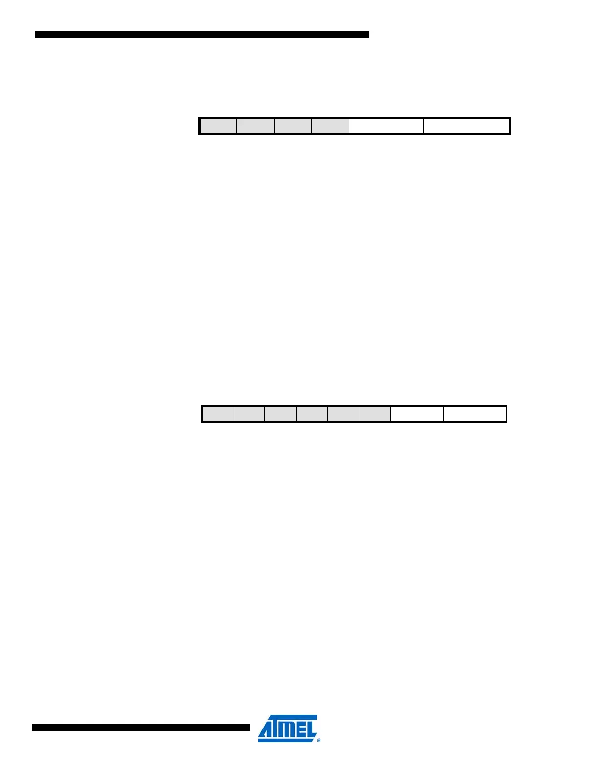
19.3.3 INTCTRL – Interrupt Control register
• Bit 7:4 – Reserved
These bits are unused and reserved for future use. For compatibility with future devices, always
write these bits to zero when this register is written.
• Bit 3:2 – COMPINTLVL[1:0]: Compare Match Interrupt Level
These bits enable the RTC32 compare match interrupt and select the interrupt level, as
described in ”Interrupts and Programmable Multilevel Interrupt Controller” on page 134. The
enabled interrupt will trigger when COMPIF in the INTFLAGS register is set.
• Bit 1:0 – OVFINTLVL[1:0]: Overflow Interrupt Level
These bits enable the RTC32 overflow interrupt and select the interrupt level, as described in
”Interrupts and Programmable Multilevel Interrupt Controller” on page 134. The enabled interrupt
will trigger when OVFIF in the INTFLAGS register is set.
19.3.4 INTFLAGS – Interrupt Flag register
• Bit 7:2 – Reserved
These bits are unused and reserved for future use. For compatibility with future devices, always
write these bits to zero when this register is written.
• Bit 1 – COMPIF: Compare Match Interrupt Flag
This flag is set on the next count after a compare match condition occurs. The flag is cleared
automatically when the RTC32 compare match interrupt vector is executed. The flag can also be
cleared by writing a one to its bit location.
• Bit 0 – OVFIF: Overflow Interrupt Flag
This flag is set on the next count after an overflow condition occurs. The flag is cleared automat-
ically when the RTC32 overflow interrupt vector is executed. The flag can also be cleared by
writing a one to its bit location.
19.3.5 CNT0 – Counter register 0
The CNT0, CNT1, CNT2, and CNT3 registers represent the 32-bit value, CNT. CNT counts pos-
itive clock edges on the RTC32 clock.
Bit 7654321 0
+0x02
– – – – COMPINTLVL[1:0] OCINTLVL[1:0] INTCTRL
Read/WriteRRRRR/WR/WR/WR/W
Reset Value0000000 0
Bit 765432 1 0
+0x03
– – – – – – COMPIF OVFIF INTFLAGS
Read/WriteRRRRRR R/W R/W
Initial Value 0 0 0 0 0 0 0 0

 Loading...


