29
8331B–AVR–03/12
Atmel AVR XMEGA AU
• Bit 3:2 – SPMLVL[1:0]: SPM Ready Interrupt Level
These bits enable the interrupt and select the interrupt level, as described in ”Interrupts and Pro-
grammable Multilevel Interrupt Controller” on page 134. This is a level interrupt that will be
triggered only when the NVMBUSY flag in the STATUS register is set to zero. Thus, the interrupt
should not be enabled before triggering an NVM command, as the NVMBUSY flag will not be set
before the NVM command is triggered. The interrupt should be disabled in the interrupt handler.
• Bit 1:0 – EELVL[1:0]: EEPROM Ready Interrupt Level
These bits enable the EEPROM ready interrupt and select the interrupt level, as described in
”Interrupts and Programmable Multilevel Interrupt Controller” on page 134. This is a level inter-
rupt that will be triggered only when the NVMBUSY flag in the STATUS register is set to zero.
Thus, the interrupt should not be enabled before triggering an NVM command, as the NVM-
BUSY flag will not be set before the NVM command is triggered. The interrupt should be
disabled in the interrupt handler.
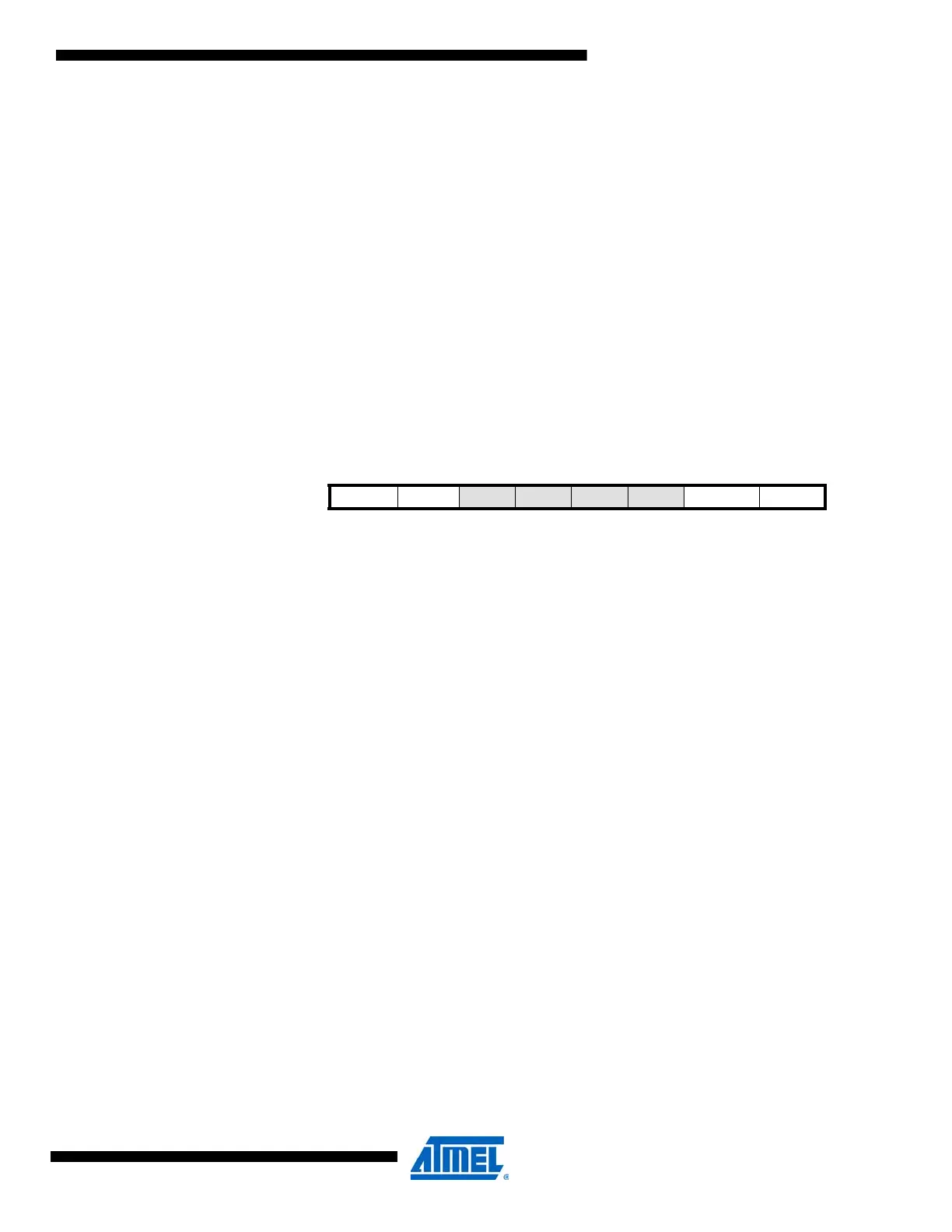
4.15.11 STATUS – Status register
• Bit 7 – NVMBUSY: Nonvolatile Memory Busy
The NVMBUSY flag indicates if the NVM (Flash, EEPROM, lockbit) is being programmed. Once
an operation is started, this flag is set and remains set until the operation is completed. The
NVMBUSY flag is automatically cleared when the operation is finished.
• Bit 6 – FBUSY: Flash Busy
The FBUSY flag indicates if a flash programming operation is initiated. Once an operation is
started the FBUSY flag is set and the application section cannot be accessed. The FBUSY flag
is automatically cleared when the operation is finished.
• Bit 5:2 – Reserved
These bits are unused and reserved for future use. For compatibility with future devices, always
write these bits to zero when this register is written.
• Bit 1 – EELOAD: EEPROM Page Buffer Active Loading
The EELOAD flag indicates that the temporary EEPROM page buffer has been loaded with one
or more data bytes. It remains set until an EEPROM page write or a page buffer flush operation
is executed. For more details see ”Flash and EEPROM Programming Sequences” on page 434.
• Bit 0 – FLOAD: Flash Page Buffer Active Loading
The FLOAD flag indicates that the temporary flash page buffer has been loaded with one or
more data bytes. It remains set until an application page write, boot page write, or page buffer
flush operation is executed. For more details see ”Flash and EEPROM Programming
Sequences” on page 434.
Bit 7 6 5432 1 0
+0x04 NVMBUSY FBUSY – – – – EELOAD FLOAD STATUS
Read/Write R R RRRR R R
Initial Value 0 0 0000 0 0

 Loading...


