322
8331B–AVR–03/12
Atmel AVR XMEGA AU
The following setup and use procedure is recommended:
1. Enable the AES interrupt (optional).
2. Select the AES direction to encryption or decryption.
3. Load the key data block into the AES key memory.
4. Load the data block into the AES state memory.
5. Start the encryption/decryption operation.
If more than one block is to be encrypted or decrypted, repeat the procedure from step 3.
When the encryption/decryption procedure is complete, the AES interrupt flag is set and an
optional interrupt is generated.
25.4.1 Key and State Memory
The AES key and state memory are both 16 x 8-bit memories that are accessible through the
KEY and STATE registers, respectively.
Each memory has two 4-bit address pointers used to address the memory for read and write,
respectively. The initial value of the pointers is zero. After a read or write operation to the STATE
or KEY register, the appropriate pointer is automatically incremented. Accessing (read or write)
the control register (CTRL) will reset all pointers to zero. A pointer overflow (a sequential read or
write done more than 16 times) will also set the affected pointer to zero. The pointers are not
accessible from software. Read and write memory pointers are both incremented during write
operations in XOR mode.
Access to the KEY and STATE registers is possible only when encryption/decryption is not in
progress.
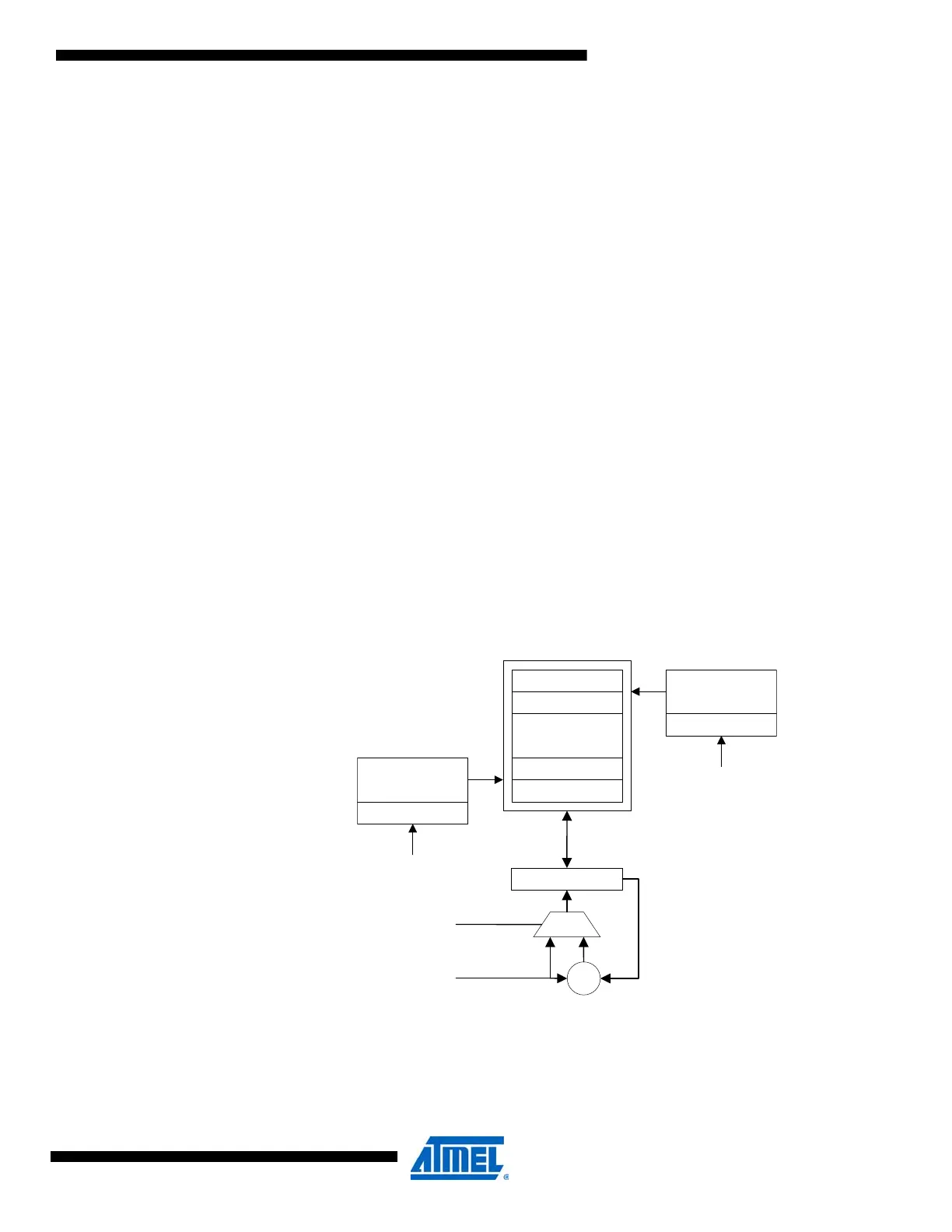
Figure 25-2. The state memory with pointers and register.
The state memory contains the AES state throughout the encryption/decryption process. The ini-
tial value of the state is the initial data (i.e., plaintext in the encryption mode, and ciphertext in the
decryption mode). The last value of the state is the encrypted/decrypted data.
4-bit state write
address pointer
1
-
14
15
STATE
0
4-bit state read
address pointer
Reset pointer
Reset pointer
reset or access
to AES Control
reset or access
to AES Control
STATE[read pointer]
xor
XOR
I/O Data Bus

 Loading...


