34
8331B–AVR–03/12
Atmel AVR XMEGA AU
4.16.5 FUSEBYTE5 – Fuse Byte 5
• Bit 7:6 – Reserved
These bits are unused and reserved for future use. For compatibility with future devices, always
write these bits to one when this register is written.
• Bit 5:4 – BODACT[1:0]: BOD Operation in Active Mode
These fuse bits set the BOD operation mode when the device is in active and idle modes. For
details on the BOD and BOD operation modes, refer to ”Brownout Detection” on page 115.
• Bit 3 – EESAVE: EEPROM is Preserved through the Chip Erase
A chip erase command will normally erase the flash, EEPROM and internal SRAM. If this fuse is
programmed, the EEPROM is not erased during chip erase. This is useful if EEPROM is used to
store data independent of the software revision.
Changes to the EESAVE fuse bit take effect immediately after the write timeout elapses. Hence,
it is possible to update EESAVE and perform a chip erase according to the new setting of
EESAVE without leaving and reentering programming mode.
• Bit 2:0 – BODLEVEL[2:0]: Brownout Detection Voltage Level
These fuse bits sets the BOD voltage level. Refer to ”Reset System” on page 113 for details. For
BOD level nominal values, see Table 9-2 on page 116.
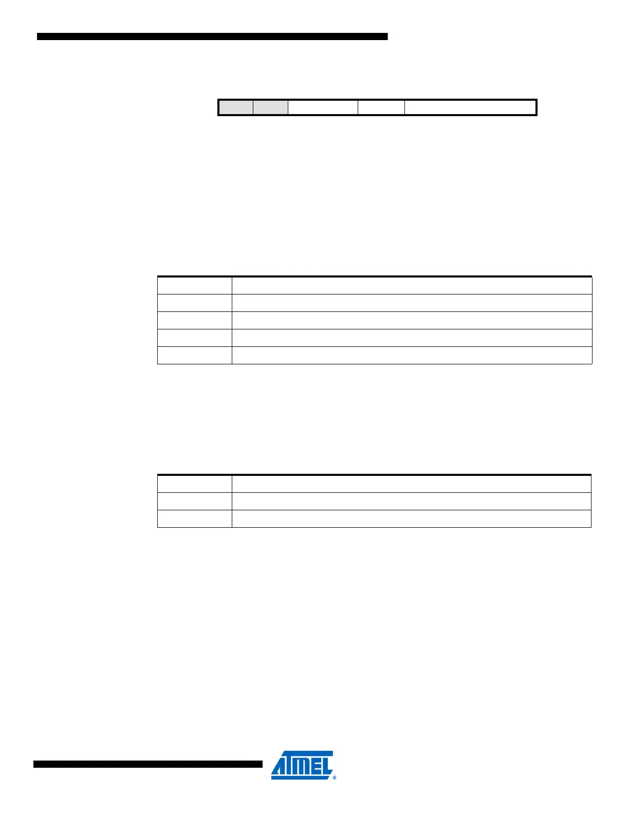
Bit 7654 3 2 1 0
+0x05 – – BODACT[1:0] EESAVE BODLEVEL[2:0] FUSEBYTE5
Read/Write R R R/W R/W R/W R/W R/W R/W
Initial Value 1 1 – – – – – –
Table 4-7. BOD operation modes in active and idle modes.
BODACT[1:0] Description
00 Reserved
01 BOD enabled in sampled mode
10 BOD enabled continuously
11 BOD disabled
Table 4-8. EEPROM preserved through chip erase
EESAVE Description
0 EEPROM is preserved during chip erase
1 EEPROM is erased during chip erase

 Loading...


