391
8331B–AVR–03/12
Atmel AVR XMEGA AU
• Bit 4:2 – Reserved
These bits are unused and reserved for future use. For compatibility with future devices, always
write these bits to zero when this register is written.
• Bit 1 – CH1TRIG: Auto trigged mode Channel 1
If this bit is set, an event on the configured event channel, set in EVCTRL, will trigger a conver-
sion on DAC channel 1 if its data register, CH1DATA, has been updated.
• Bit 0 – CH0TRIG: Auto trigged mode Channel 0
If this bit is set, an event on the configured event channel, set in EVCTRL, will trigger a conver-
sion on DAC channel 0 if its data register, CH0DATA, has been updated.
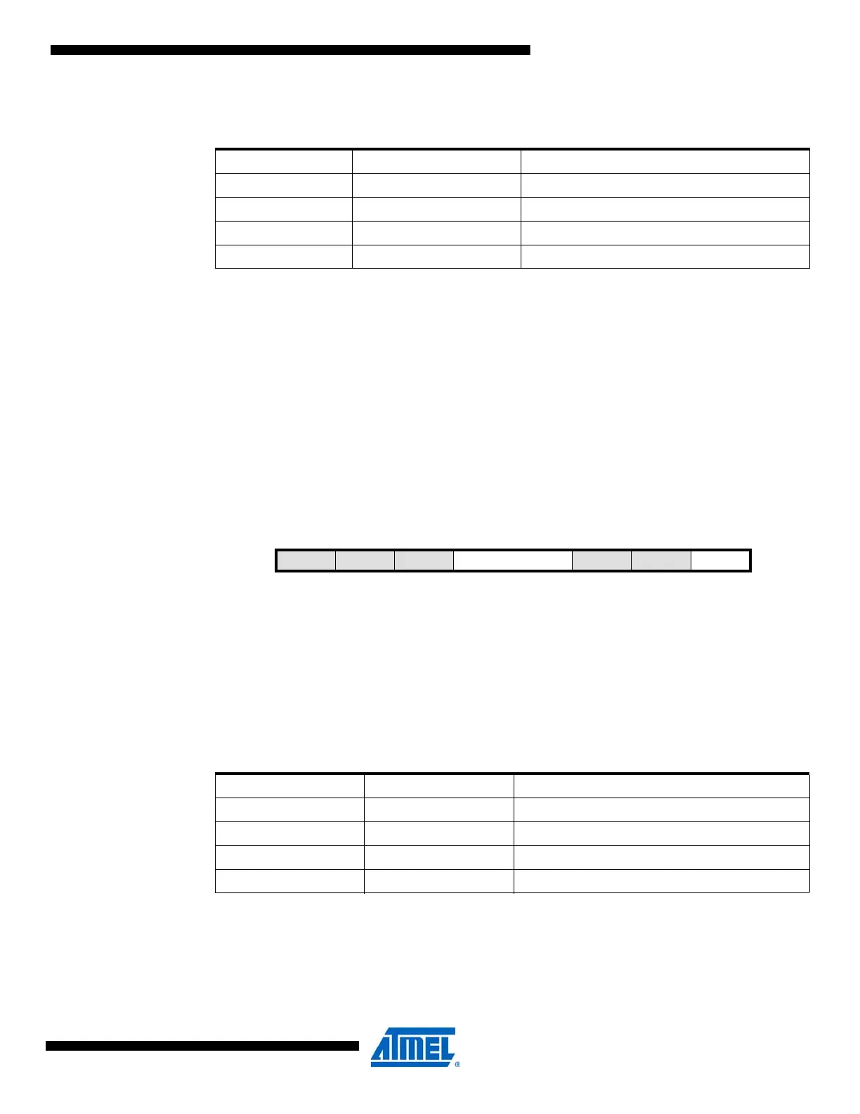
29.10.3 CTRLC – Control Register C
• Bit 7:5 – Reserved
These bits are unused and reserved for future use. For compatibility with future devices, always
write these bits to zero when this register is written.
• Bit 4:3 – REFSEL[1:0]: Reference Selection
These bits select the reference voltage for the DAC according to Table 29-2 on page 391.
• Bit 2:1 – Reserved
These bits are unused and reserved for future use. For compatibility with future devices, always
write these bits to zero when this register is written.
Table 29-1. DAC channel selection
CHSEL[1:0] Group Configuration Description
00 SINGLE Single-channel operation on channel 0
01 SINGLE1 Single-channel operation on channel 1
10 DUAL Dual-channel operation
11 – Reserved
Bit 76543210
+0x02 – – – REFSEL[1:0] – – LEFTADJ CTRLC
Read/WriteRRRR/WR/WRRR/W
Initial Value00000000
Table 29-2. DAC Reference selection.
REFSEL[1:0] Group Configuration Description
00 INT1V Internal 1.00V
01 AVCC AV
CC
10 AREFA AREF on PORTA
11 AREFB AREF on PORTB
 Loading...


