81
8331B–AVR–03/12
Atmel AVR XMEGA AU
6.8.3 STROBE – Strobe register
If the STROBE register location is written, each event channel will be set according to the
STROBE[n] and corresponding DATA[n] bit settings, if any are unequal to zero.
A single event lasting for one peripheral clock cycle will be generated.
6.8.4 DATA – Data register
This register contains the data value when manually generating a data event. This register must
be written before the STROBE register. For details, See ”STROBE – Strobe register” on page
81.
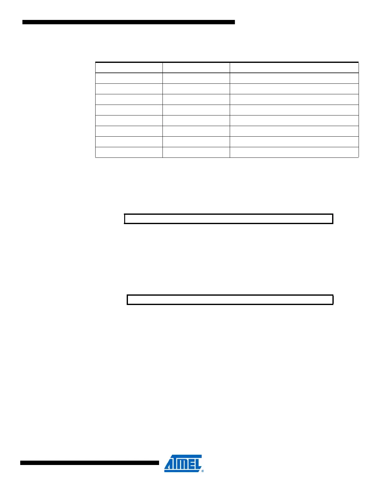
Table 6-6. Digital filter coefficient values .
DIGFILT[2:0] Group Configuration Description
000 1SAMPLE One sample
001 2SAMPLES Two samples
010 3SAMPLES Three samples
011 4SAMPLES Four samples
100 5SAMPLES Five samples
101 6SAMPLES Six samples
110 7SAMPLES Seven samples
111 8SAMPLES Eight samples
Bit 76543210
+0x10 STROBE[7:0] STROBE
Read/Write R/W R/W R/W R/W R/W R/W R/W R/W
Initial Value 00000000
Bit 76543210
+0x11 DATA[7:0] DATA
Read/Write R/W R/W R/W R/W R/W R/W R/W R/W
Initial Value 00000000
 Loading...


