95
8331B–AVR–03/12
Atmel AVR XMEGA AU
• Bit 0 – RTCEN: RTC Clock Source Enable
Setting the RTCEN bit enables the selected RTC clock source for the real-time counter.
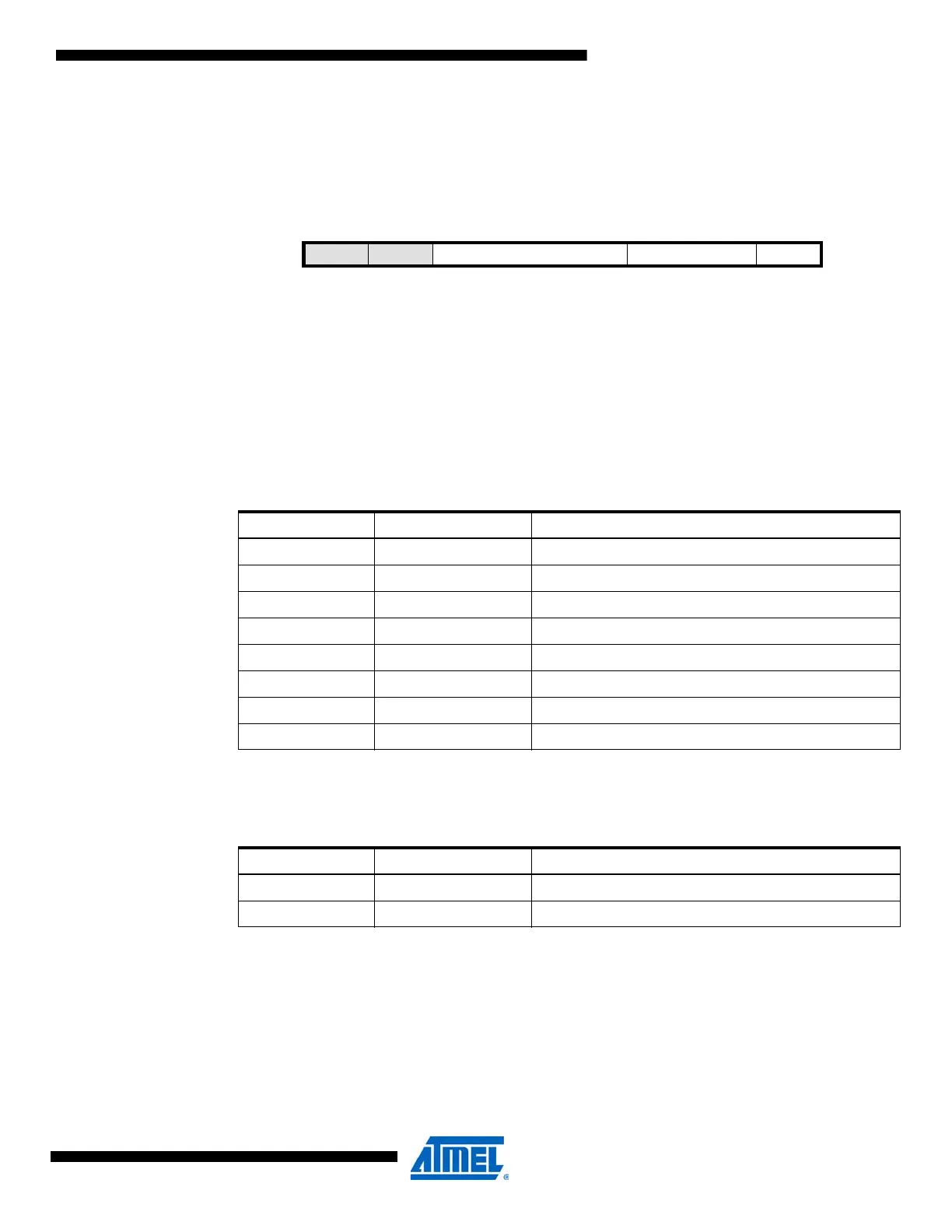
7.9.5 USBSCTRL – USB Control register
• Bit 7:6 – Reserved
These bits are unused and reserved for future use. For compatibility with future devices, always
write these bits to zero when this register is written.
• Bit 5:3 – USBPSDIV[2:0]: USB Prescaler Division Factor
These bits define the division ratio of the USB clock prescaler according to Table 7-5 on page
95. These bits are locked as long as the USB clock source is enabled.
• Bit 2:1 – USBSRC[1:0]: USB Clock Source
These bits select the clock source for the USB module according to Table 7-6 on page 95.
Note: 1. The 32MHz internal oscillator must be calibrated to 48MHz before selecting this as source for
the USB device module. Refer to ”DFLL 2MHz and DFLL 32MHz” on page 89.
• Bit 0 – USBSEN: USB Clock Source Enable
Setting this bit enables the selected clock source for the USB device module.
Bit 76543210
+0x04
– – USBPSDIV[2:0] USBSRC[1:0] USBSEN USBSCTRL
Read/Write R R R/W R/W R/W R/W R/W R/W
Initial Value00000000
Table 7-5. USB prescaler division factor.
USBPSDIV[2:0] Group Configuration Description
000 1 No division
001 2 Divide by 2
010 4 Divide by 4
011 8 Divide by 8
100 16 Divide by 16
101 32 Divide by 32
110 — Reserved
111 — Reserved
Table 7-6. USB clock source.
USBSRC[1:0] Group Configuration Description
00 PLL PLL
01 RC32M 32MHz internal oscillator
(1)

 Loading...


