Page 4–206
DURApulse GS4 AC Drive User Manual – 1st Ed, Rev A - 10/20/2017
Chapter 4: AC Drive Parameters
grouP P11.xx details – Fault ParaMeters
Type Hex Addr Dec Addr
P11.00 Fault Output Option 1
♦R/W 0B00 42817
P11.01 Fault Output Option 2
♦R/W 0B01 42818
P11.02 Fault Output Option 3
♦R/W 0B02 42819
P11.03 Fault Output Option 4
♦R/W 0B03 42820
Range/Units (Format: 16-bit unsigned) Default
0: No Error
1~65535: (refer to Fault Bit Codes table)
0
These parameters can be used with a Multi-Function Output set to 33~36 for a specific monitoring
requirement. When a fault occurs, the corresponding MFO terminals will be activated. Each Fault
option parameter can contain multiple monitord bits. Parameter can contain up to 127decimal
(7F hex or 1111111 binary). Values are entered in decimal.
Related parameters: P3.17~P3.31 (page 4–74)
Example: If DO1=36 (FO1) and P11.00 (FO1) = 34 (22 hex, 0100010 bin), then when an external fault
(EF, EF1, bb..) or a voltage related fault occurs DO1 will be activated.
Representation of bits:
•
Bit0: Current-related fault
•
Bit1: Voltage-related fault
•
Bit2: Overload-related fault
•
Bit3: System-related fault
•
Bit4: Feedback-related fault
•
Bit5: External Fault-related fault
•
Bit6: Communication-related fault
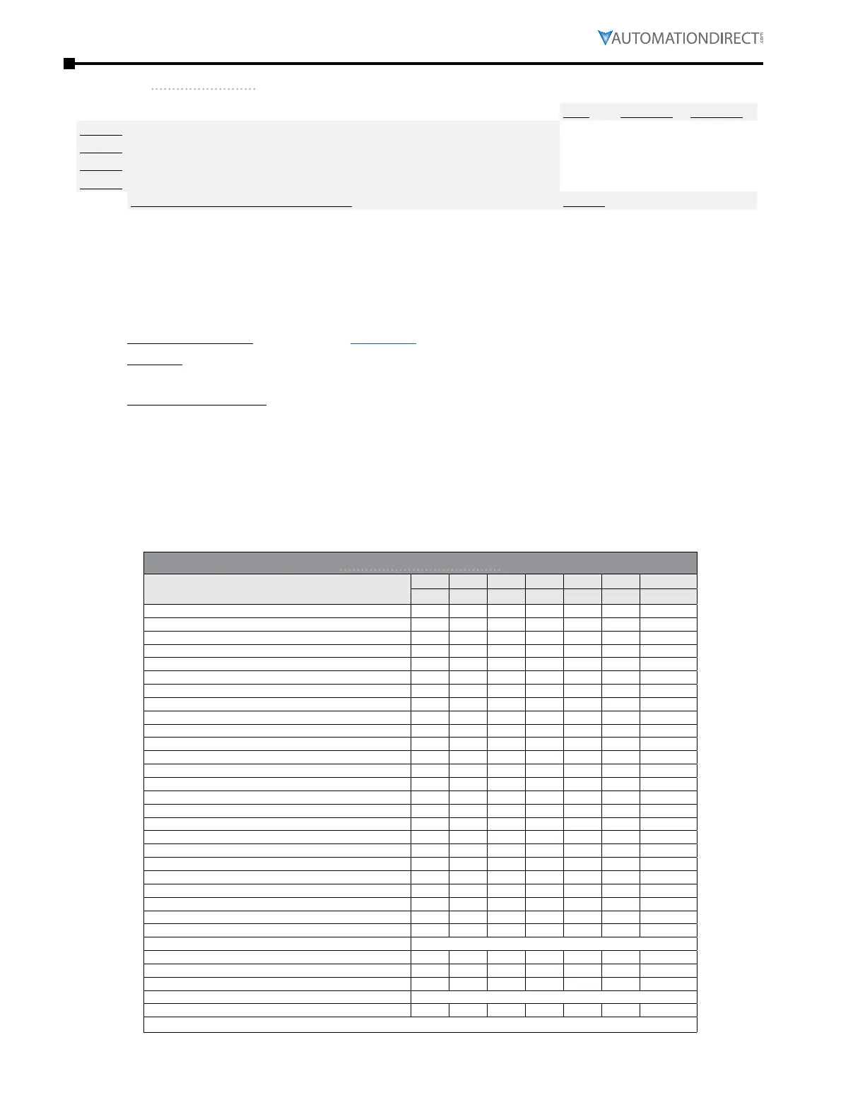
Table of Fault Bit Codes
Fault Code
Bit6 Bit5 Bit4 Bit3 Bit2 Bit1 Bit0
CE EXI FBK SYS OL Volt Current
0: No Error
1: Overcurrent during Accel (ocA) •
2: Overcurrent during Decel (ocd) •
3: Overcurrent during normal speed (ocn) •
4: Ground Fault (GFF) •
5: IGBT short circuit (occ) •
6: Overcurrent during Stop (ocS) •
7: Overvoltage during Accel (ovA) •
8: Overvoltage during Decel (ovd) •
9: Overvoltage during normal speed (ovn) •
10: Overvoltage during Stop (ovS) •
11: Low voltage during Accel (LvA) •
12: Low voltage during Decel (Lvd) •
13: Low voltage during normal speed (Lvn) •
14: Low voltage during Stop (LvS) •
15: Outout ripple / Input phase loss (OrP) •
16: IGBT Overheat 1 (oH1) •
17: Cap Overheat 2 (oH2) •
18: Thermister 1 open (tH1o) •
19: Thermister 2 open (tH2o) •
20: Power Reset Off (PWR) •
21: Overload (oL) (150% 1Min, Inverter) •
22: Motor1 Thermal Overload (EoL1) •
23: Motor2 Thermal Overload (EoL2) •
24: Motor Overheat-PTC (oH3) •
25: reserved –
26: Over Torque 1 (ot1) •
27: Over Torque 2 (ot2) •
28: Under current (uc) •
29: reserved –
30: EEPROM write error (cF1) •
(table continued next page)

 Loading...
