MFC-8220
SERVICE MANUAL
4-47
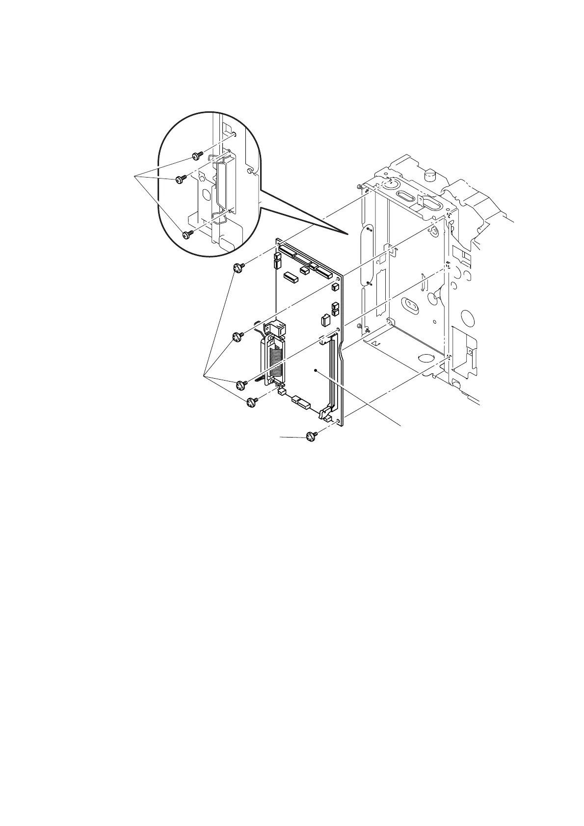
(3) Remove the three pan M3x6 screws.
(4) Remove the five cup S M3x6 Taptite screws, and then remove the main PCB ASSY.
Fig. 4-85
NOTE:
After replacing the Main PCB, please perform the following operations.
• Chapter 7 3.12 CIS Scanner Area Setting (Maintenance mode 55) (Refer to P7-20.)
• APPENDIX 1 EEPROM CUSTOMIZING CODES (Refer to A-1.)
• APPENDIX 2.1 INSTALING THE UPDATE DATA TO THE MACHINE (Refer to A-2.)
• APPENDIX 2.2 SETTING ID CODES TO MACHINES (Refer to A-4.)
Main PCB ASSY
Taptite, cup S M3x6
Taptite, cup S M3x6
Screw, pan
M3x6
 Loading...