CHAPTER 4 DISASSEMBLY AND RE-ASSEMBLY
4-46
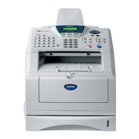
(5) Remove the shutter arm C.
Fig. 4-83
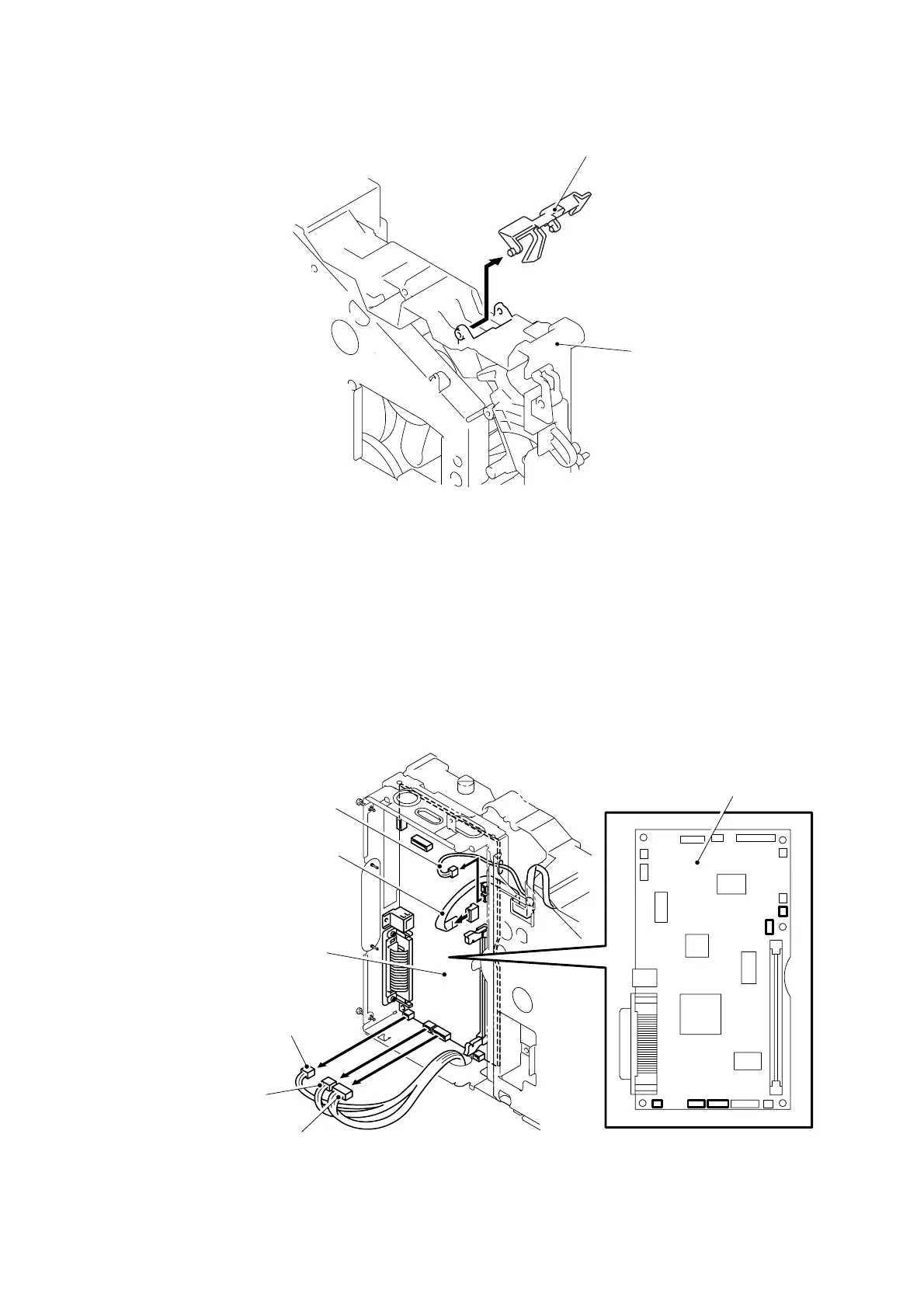
3.16 Main PCB ASSY
(1) Disconnect the LD harness 5P.
NOTE:
• After disconnecting flat cable(s), check that each cable is not damaged at its end or
short-circuited.
• When connecting flat cable(s), do not insert them at an angle. After insertion, check
that the cables are not at an angle.
(2) Disconnect the four connectors.
Fig. 4-84
Shutter arm C
Frame L
Main PCB ASSY
Panel PCB connector
Engine PCB connector
LVPS connector
Thermistor connector
LD harness 5P
Main PCB ASSY
 Loading...