CHAPTER 4 DISASSEMBLY AND RE-ASSEMBLY
4-50
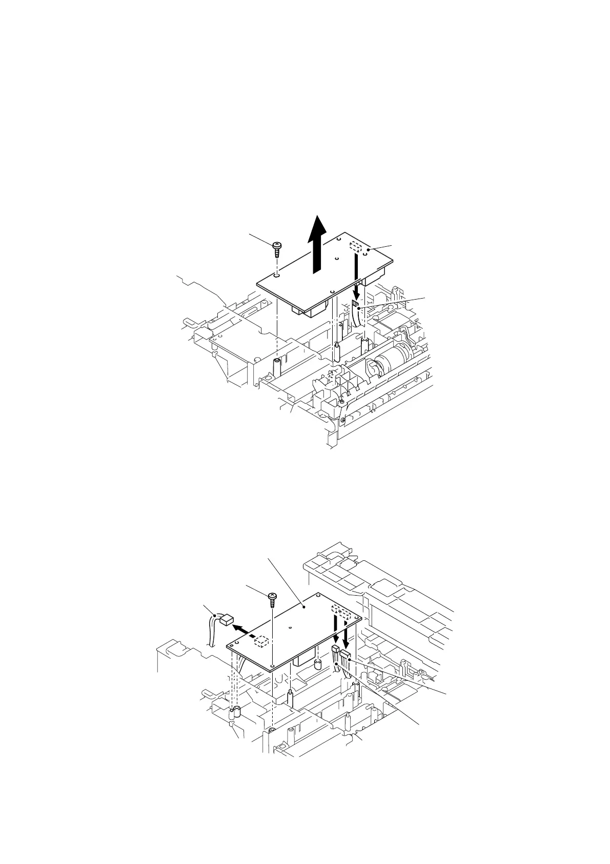
3.19 High-voltage PS PCB ASSY
(1) Remove the bind B M4x12 Taptite screw, and then remove the high-voltage PS PCB
ASSY.
(2) Disconnect the flat cable from the high-voltage PS PCB ASSY.
NOTE:
• After disconnecting flat cable(s), check that each cable is not damaged at its end or
short-circuited.
• When connecting flat cable(s), do not insert them at an angle. After insertion, check
that the cables are not at an angle.
Fig. 4-90
3.20 Low-voltage PS PCB ASSY
(1) Remove the bind B M4x12 Taptite screw.
(2) Disconnect the three connectors from the low-voltage PS PCB, and then remove the low-
voltage PS PCB ASSY.
Fig. 4-91
Main PCB/Engine
PCB connector
Heater connector
Taptite, bind B M4x12
Low-voltage PS PCB ASSY
Taptite, bind B M4x12
Flat cable
High-voltage PS PCB ASSY
Main PCB connector
 Loading...