MFC-8220
SERVICE MANUAL
4-49
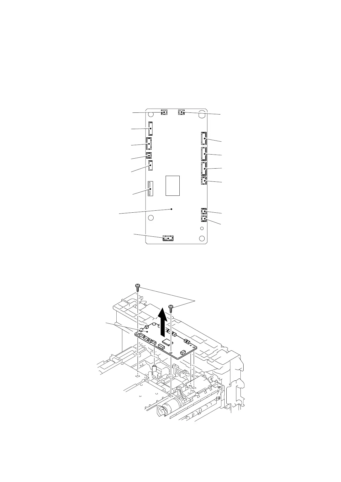
3.18 Engine PCB ASSY
(1) Disconnect the connectors.
NOTE:
• After disconnecting flat cable(s), check that each cable is not damaged at its end or
short-circuited.
• When connecting flat cable(s), do not insert them at an angle. After insertion, check
that the cables are not at an angle.
Fig. 4-88
(2) Remove the two bind B M4x12 Taptite screws, and then remove the engine PCB ASSY.
Fig. 4-89
Taptite, bind B M4x12
Engine PCB ASSY
Engine PCB ASSY
Toner sensor
(light reception) connector
Thermistor relay PCB connector
Main motor connector
Main PCB connector
FR solenoid connector
PF solenoid connector
Fan motor 60 unit connector
LT connector
Polygon motor connector
Fan motor 60 connector
LVPS PCB connector
Cassette sensor PCB connector
Toner sensor
(light emission) connector
HVPS PCB connector
 Loading...