122
Auxiliary functions
26.2.14.2. OUT BIN1 / OUT BIN2 - Configuring the binary outputs
The following description is valid for both binary outputs OUT BIN 1 and OUT BIN 2, as the operation in the menu
is identical.
The binary outputs 1 and 2 can be used for one of the following outputs:
POS.Dev
Exceeding the permitted control deviation
POS.Lim-1/2
Current position with respect to a specified limit position (> or <)
Safepos
Actuator in safety position
ERR.SP/CMD
Sensor break (SP = process set-point value / CMD = set-point value position)
ERR.PV
Sensor break (process actual value). Available for Type 8793 only.
Remote
Operating state (AUTOMATIC / MANUAL)
Tune.Status
Status X.TUNE (process optimization)
DIAG.State-1/2
Diagnosis output (option)
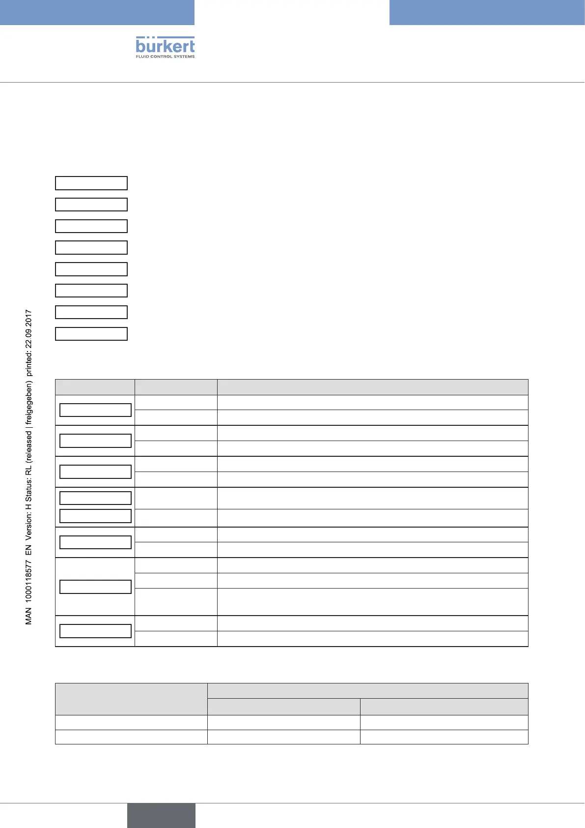
Overview of possible outputs and associated switching signals:
Menu option Switching signal Description
POS.Dev
0 Control deviation is within the set limit.
1 Control deviation is outside the set limit.
POS.Lim-1/2
0 Actual position is above the limit position.
1 Actual position is below the limit position.
Safepos
0 Actuator is not in the safety position.
1 Actuator is in the safety position.
ERR.SP/CMD
0 No sensor break available.
ERR.PV
1 Sensor break available.
Remote
0 Appliance is the AUTOMATIC operating state.
1 Appliance is the MANUAL operating state.
Tune.Status
0 The X.TUNE function is currently not running.
1 The X.TUNE function is currently running.
0/1 alternating
(10 s)
The X.TUNE function was stopped during execution by a fault.
DIAG.State-1/2
0 No diagnosis message available for the selected status signals.
1 Diagnosis message available for the selected status signals.
Table 57: OUT BIN 1/2; Possible outputs and associated switching signals
Switching signal
Switching statuses
normally open normally closed
0
0 V 24 V
1
24 V 0 V
Table 58: OUT BIN 1/2; switching statuses