CRITICALPOINT 700/800MHZ BDA/DAS/BBU V3 USER MANUAL
©2024 Comba Telecom. All Rights Reserved.
568 Gibraltar Drive, Milpitas, CA 95035 | +1 408 526 0180
Rev. 1-0-2 Rev. Date: 11-1-2024
3.2 REQUIRED RF INPUTS FOR COMMISSIONING
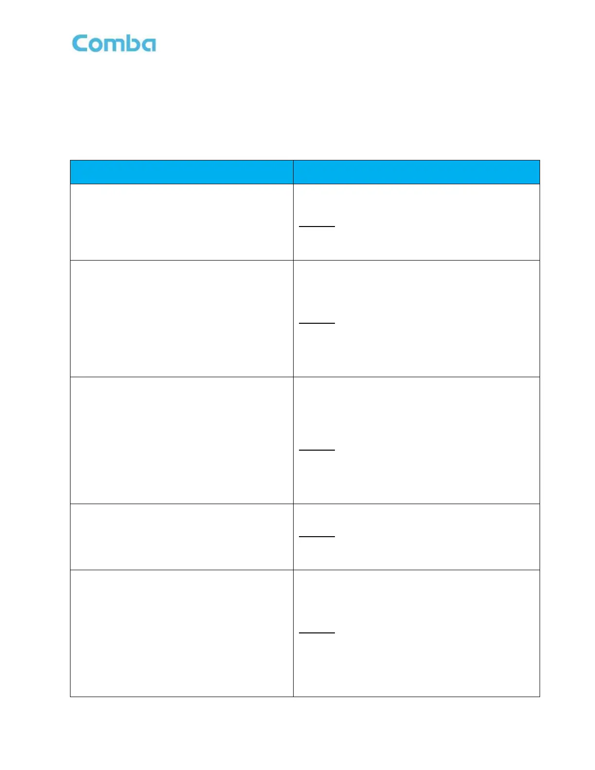
Users are encouraged to gather the information below before commissioning the system. See Table 10
below which provides an explanation of the recommended inputs which should be gathered and their
purpose in commissioning the system.
Table 10: Required RF Inputs for Commissioning
Provided by AHJ and/or FCC/ISED License Holder.
The Effective Radiated Power of each channel from the
Donor Site.
Example: 100 Watts / 50dBm per Radio Channel
Used in calculations to estimate the total DL and UL
pathloss between the donor site and BDA.
Donor Site TX/RX Delta (dB)
Provided by AHJ and/or FCC/ISED License Holder.
The difference in donor pathloss between the DL and UL
paths; due to RF Gain components on the donor site receive
side such as RX Antennas, Tower Top Amplifiers, and RX
Multi-couplers.
Example: Donor Site TX/RX Delta is -15dB due to an
additional 15dB of Gain provided by RF components on the
receiver side.
Used in calculations to estimate the total UL pathloss
between the BDA and donor site.
Donor Site RX RSSI (dBm)
(Maximum and Minimum)
Provided by AHJ and/or FCC/ISED License Holder.
The required RSSI Range at Donor Site (Minimum and
Maximum).
If only a minimum is provided, you can use the same
number for the minimum and maximum.
Example: >-95dBm is required.
MAX RSSI = -95dBm
MIN RSSI = -95dBm
Used in calculations to estimate the UL Channel Target
Power and UL MAX Gain.
BDA Donor Antenna Gain (dBd)
Refer to Datasheet of Installed Donor Antenna.
The Gain of the Donor Antenna expressed in dBd.
Example:12dBd / 14.15dBi
Used in calculations to estimate the DL and UL pathloss
between the donor site and BDA.
BDA Donor Cable Loss (dB)
Provided by the System Design or Manual Measurement
The total passive loss between the Donor Antenna and BDA
Donor Terminal; due to passive components such as cables
and surge arrestors.
Example:
½ in Donor Cable Length: 100ft (2.2dB/100ft)
Surge Arrestor Insertion Loss: 0.2dB
Donor Cable Loss = 2.2dB + 0.2dB = 2.4dB
Used in calculations to estimate the DL and UL pathloss
between the donor site and BDA.