©2024 Comba Telecom. All Rights Reserved.
568 Gibraltar Drive, Milpitas, CA 95035 | +1 408 526 0180
Commissioning Tool Results:
• To generate the suggested values for DL_GAIN, DL_TAR, UL_GAIN, and UL_TAR, you must click
on the <Generate> button in the commissioning tool window.
View the results in the lower window of the commissioning tool. The suggested values are for
reference only. The result will NOT apply to any filters. Users need to manually apply the values if
they are satisfied with the procedure results. Results should be compared to System Design and
inconsistencies should be reviewed before commissioning and turning on the RF Switches.
Figure 136: Commissioning Tool – Viewing the Suggested RF Parameters
3.28 POWER, GAIN, ATTENUATION, AND AGC/ALC CONTROLS
BDA Diagram and RF Parameters
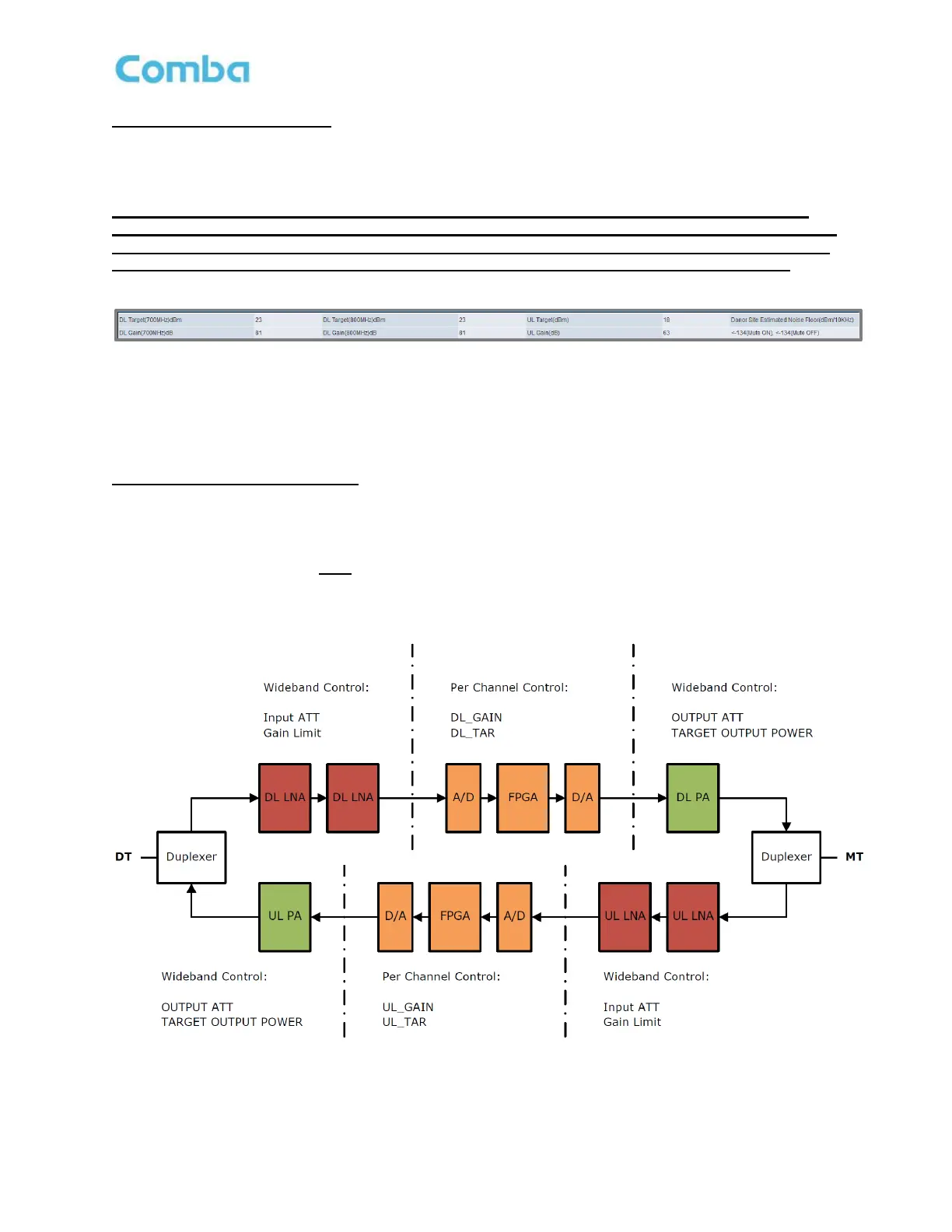
The V3 BDA has multiple parameters to control the gain and power and provides AGC/ALC to limit the output
power. See Figure 137 and Table 19 for a detailed description of these parameters.
Note: The diagram below is NOT depicting the actual block diagram of the system but is a simplified
diagram showing the approximate function of each parameter.
Figure 137: Commissioning BDA – Power, Gain, and Attenuation BDA Block Diagram
 Loading...